Fuel Tank Assembly
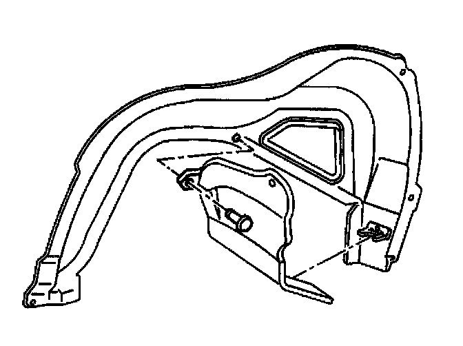
Fuel Tank Components:
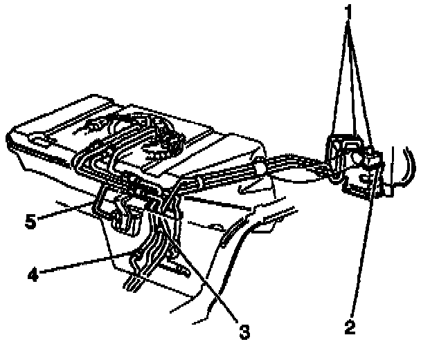
Tank Electrical Connections:
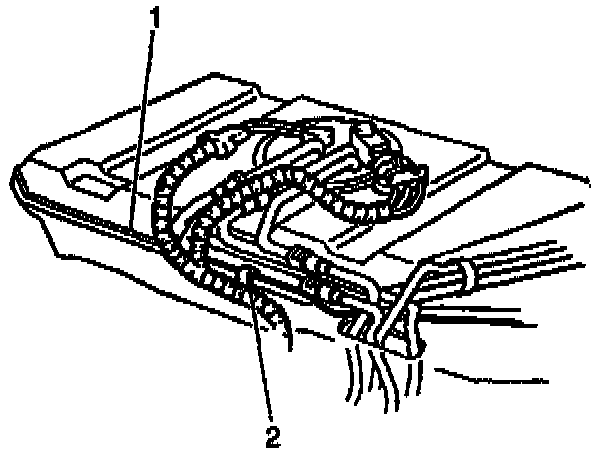
Tank Straps:
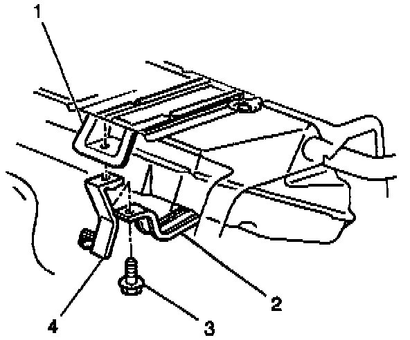
Straps:
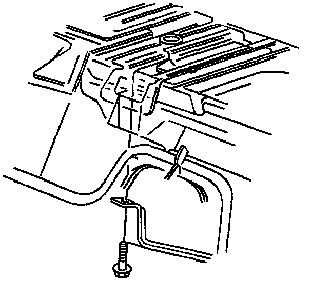
REMOVAL PROCEDURE
Caution:
- Provide additional support when a vehicle is on a hoist in the following ways:
- Before removing parts, support the opposite end. This helps prevent the vehicle from slipping off.
- Before removing major components, chain the vehicle frame to the hoist pads at the same end as the removal This helps avoid a tip-off.
- Failure to follow these precautions could cause vehicle damage, serious personal injury, or death.
1. Disconnect the negative battery cable.
2. Perform the Fuel Pressure Release Procedure.
3. Drain the fuel tank.
4. Remove the fuel tank filler pocket.
5. Raise the vehicle.
6. Remove the fuel filler pipe shield.
7. Remove the exhaust system from the catalytic converter back.
8. Remove the exhaust pipe heat shield and the exhaust muffler heat shield.
9. Remove the rear axle assembly.
10. Clean all fuel pipe connections and surrounding areas before disconnecting the fuel pipes in order to avoid possible contamination of the fuel system.
11. Disconnect the [1][2]EVAP pipes (1) at the EVAP canister (2).
12. Disconnect the fuel return pipe (4).
13. Disconnect the [1][2]EVAP purge pipe (3).
14. Disconnect the fuel feed pipe at the fuel filter inlet.
15. Disconnect the fuel tank vent valve from the rear brake hose bracket.
16. Remove the rear pipe clip.
17. Disconnect the fuel sender and the fuel pressure sensor electrical connectors.
18. Disconnect the electrical harness clip (2) from the fuel tank flange (1).
19. With the aid of an assistant, support the fuel tank.
20. Remove the left fuel tank strap attaching bolt (3) from the underbody bracket (1).
- Do not bend the fuel tank straps. Bending the fuel tank straps may damage the straps.
21. Lower the left fuel tank strap (2).
22. Remove the EVAP canister vent solenoid and bracket (4).
23. Remove the right fuel tank strap attaching bolt.
24. Lower the right fuel tank strap.
25. Remove the fuel tank.
26. Place the fuel tank in a suitable work area.
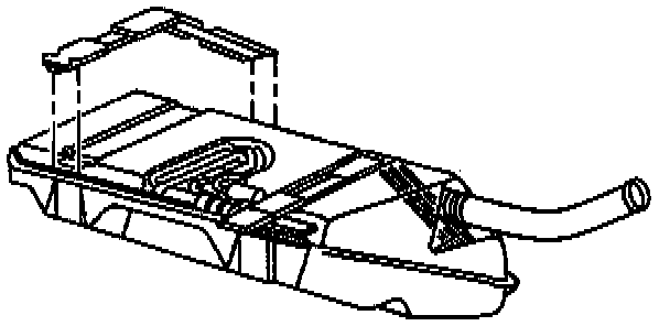
Tank Insulators:
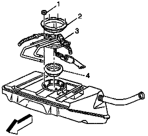
Fuel Sender Assembly:
27. Remove the fuel tank insulators if necessary.
28. Remove the fuel sender assembly (3) and the rear fuel and [1][2]EVAP pipes from the fuel tank.
INSTALLATION PROCEDURE
1. Install the fuel sender assembly (3) and the rear fuel and [1][2]EVAP pipes to the fuel tank.
Description:
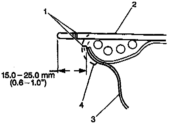
2. Install the right fuel tank insulator.
- The fuel sender pipes must route below the left fuel tank insulator.
3. Align the insulator (2) on the top of the fuel tank with 15-25 mm (O.6 - 1.0 in) of the insulator extending beyond the edge of the fuel tank front flange (3).
4. Fold the insulator down.
5. Secure the insulator to the flange (4). The alignment notch on the insulator lines up with the fuel tank flange edge (1).
6. With the aid of an assistant, position and support the fuel tank.
7. Position the right fuel tank strap up.
8. Install the front right fuel tank strap attaching bolt.
9. Position the EVAP canister vent solenoid bracket (4) between the left fuel tank strap (2) and the underbody bracket (1).
10. Install the front left fuel tank strap attaching bolt.
Tighten
Bolts to 33 Nm (24 lb ft).
11. Connect the fuel sender and the fuel pressure sensor electrical connectors.
12. Connect the electrical harness clip (2) to the fuel tank flange (1).
13. Connect the fuel tank vent valve to the rear brake hose bracket.
14. Connect the fuel feed pipe at the fuel filter inlet.
15. Connect the [1][2]EVAP purge pipe (3).
16. Connect the fuel return pipe (4).
17. Connect the [1][2]EVAP pipes (1) at the EVAP canister (2).
18. Install the fuel and [1][2]EVAP pipes into the pipe clip.
19. Align the fuel and [1][2]EVAP pipes in a flat position.
20. Install the pipe clip bolt.
Tighten
Bolt to 5.5 Nm (49 lb in).
21. Install the rear axle assembly.
22. Install the exhaust system heat shields and attaching screws.
23. Install the exhaust system.
24. Install the fuel filler pipe shield.
25. Lower the vehicle.
26. Install the fuel tank filler pocket.
27. Refill the fuel tank.
28. Install the fuel tiller cap.
29. Connect the negative battery cable.
30. Inspect for leaks.
A. Turn the ignition switch ON for 2 seconds.
B. Turn the ignition switch OFF for 10 seconds.
C. Turn the ignition switch ON.
D. Visually Inspect the fuel system for fuel leaks.