Engine Cranks, But Will Not Run
1 Of 3:
2 Of 3:
3 Of 3:
Description
The Engine Cranks but Does Not Run diagnostic table assumes that battery condition and engine cranking speed are OK. If the battery condition and the cranking speed are not OK, refer to Charging System Check and/or Starting System Check for diagnosis. Make sure that there is adequate fuel in the tank.
Diagnostic Aids
Important:
- Remove any debris from the PCM connector surfaces before servicing the PCM. Inspect the PCM connector gaskets when diagnosing/replacing the PCM. Ensure that the gaskets are installed correctly. The gaskets prevent water intrusion into the PCM.
- For any test that requires probing the PCM or component harness connectors, use the Connector Test Adapter Kit J 35616-A. Using this kit prevents damage to the harness connector terminals.
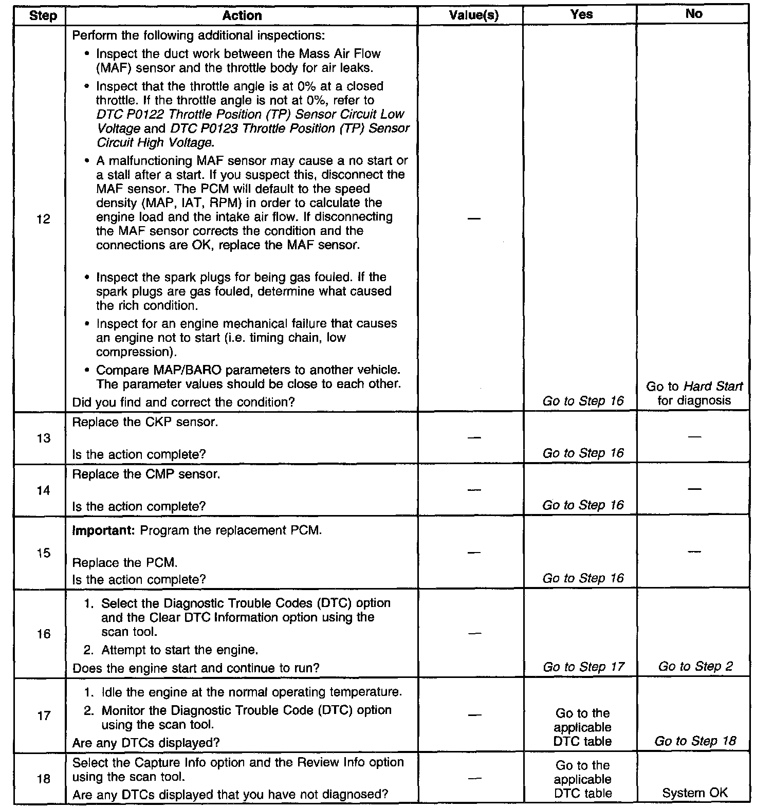
- Inspect the duct work between the Mass Air Flow (MAF) sensor and the throttle body for air leaks.
- A malfunctioning MAF sensor may cause a no start or a stall after start. It you suspect this, disconnect the MAF sensor. The PCM will default to the speed density (MAP, IAT, RPM) in order to calculate the load and the air flow. If this corrects the condition and the connections are OK, replace the MAF sensor.
If the steps above do not isolate the condition, refer to Symptoms.
Test Description
The numbers below refer to the step numbers on the diagnostic table.
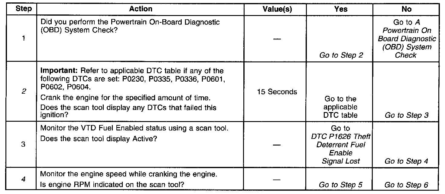
2. Certain DTCs only set while cranking the engine. This step verifies if a component is causing the no start condition.
4. This step is testing for a grounded ignition teed circuit for the crankshaft position sensor and the camshaft position sensor. When the ignition feed circuit is shorted, a no start occurs and no DTCs are set. The ignition feed circuits are connected internally within the PCM. The PCM cannot detect that the engine is cranking with a grounded ignition feed circuit. If no engine speed is displayed on the scan tool, inspect the ignition feed circuit for a short to ground.
The scan tool may reset if the battery is at a low state of charge. The battery may need to be charged to perform this step.
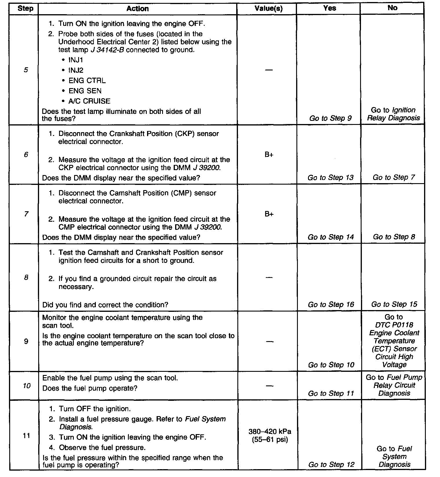
5. This step verifies the IGN relay for proper operation. The IGN relay supplies voltage to the injectors and the ignition coils. When the IGN relay is not operating properly, a no start condition occurs. If the test lamp does not illuminate, this indicates the IGN relay is not suppling a voltage to the fuses.
6. The Crankshaft Position sensor is located near the starter.
7. The Camshaft Position sensor is located at the rear of the engine behind the intake manifold.
8. The ignition feed circuit for the Camshaft and Crankshaft Position sensors is internally connected within the PCM. A short to ground on either circuit causes a no start condition.
10. The fuel cap may need to be removed to hear it the fuel pump is operating.