Engine Removal
REMOVAL PROCEDURE^ Tools Required
- J39580 Engine Support Table
- J36221 Hydraulic Clutch Line Separator
- J39549 Ball Joint/Tie Rod Separator
- J21366 Converter Holding Strap
- J39411 Flywheel Holding Tool
CAUTION: Refer to Battery Disconnect Caution in Service Precautions.
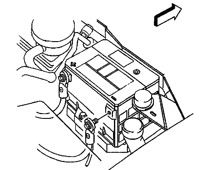
1. Disconnect the negative battery cable.
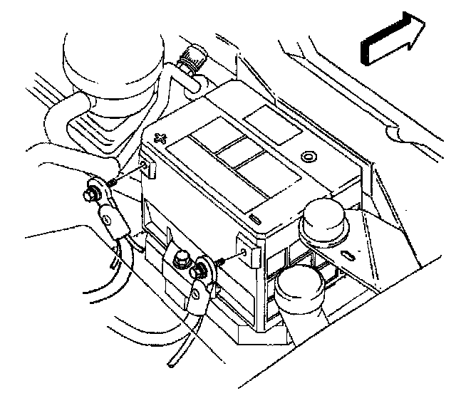
2. Disconnect the positive battery cable.
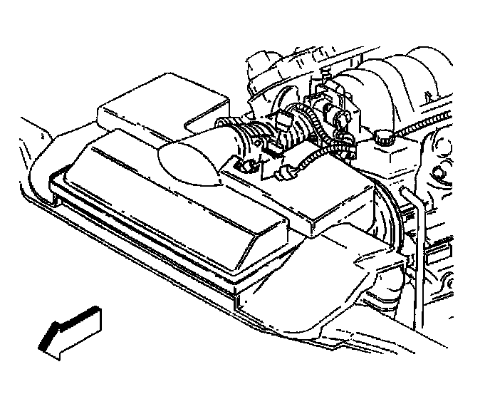
3. Disconnect the Intake Air Temperature (IAT) sensor electrical connector.
4. Disconnect the Mass Airflow (MAF) sensor electrical connector.
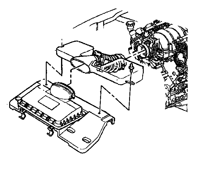
5. Remove the air intake duct resonator.
6. Recover the refrigerant.
7. Relieve the fuel pressure.
8. Raise and suitably support the vehicle.
9. Drain the engine oil.
10. Remove the front wheels.
11. Drain the engine coolant.
12. Remove the right side oxidation catalytic converter.
13. Drain the transmission fluid, if equipped with a manual transmission.
14. Remove the propeller shaft.
15. Remove the torque arm.
16. Remove the starter motor.
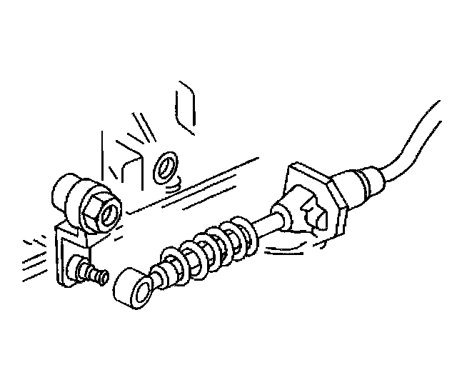
17. On vehicles equipped with a automatic transmission, unsnap the transmission range selector lever cable from the range selector lever at the transmission.
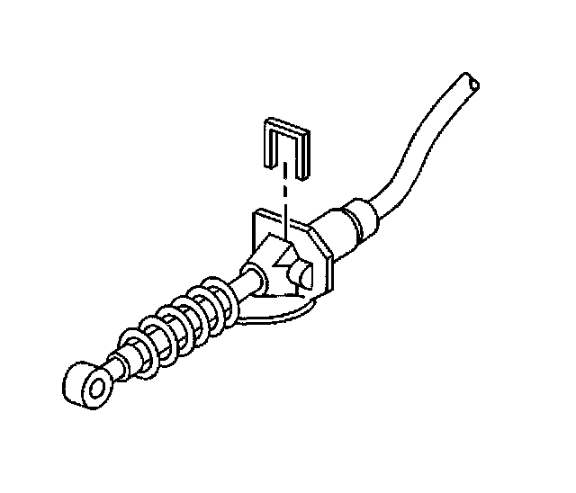
18. Remove the retainer from the range selector lever cable.
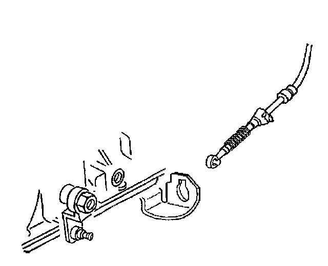
19. Remove the range selector lever cable from the cable bracket.
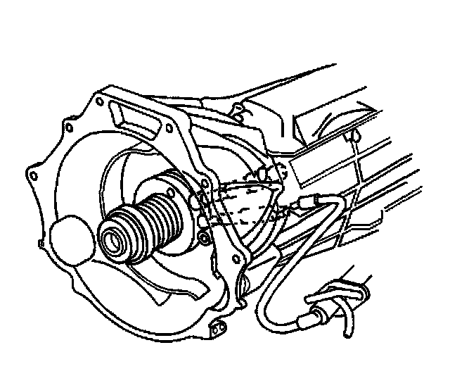
20. On vehicles equipped with a manual transmission disconnect the clutch actuator cylinder line from the actuator cylinder using J36221.
21. Remove the left side front air deflector.
22. Remove the stabilizer bar bracket bolts.
23. Remove the stabilizer bar brackets.
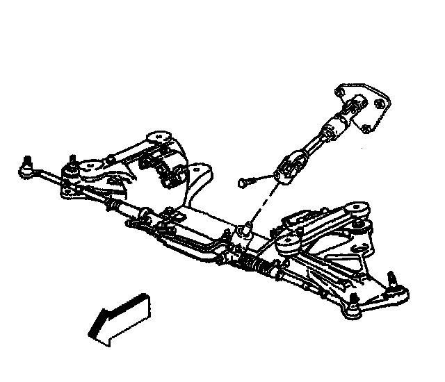
24. Remove the intermediate steering shaft bolt and shaft from the rack.
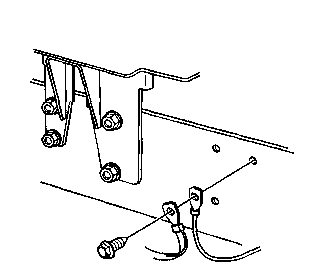
25. Remove the wiring harness ground bolt and RF (Radio Frequency) ground strap and cruise control ground lead from the front rail.
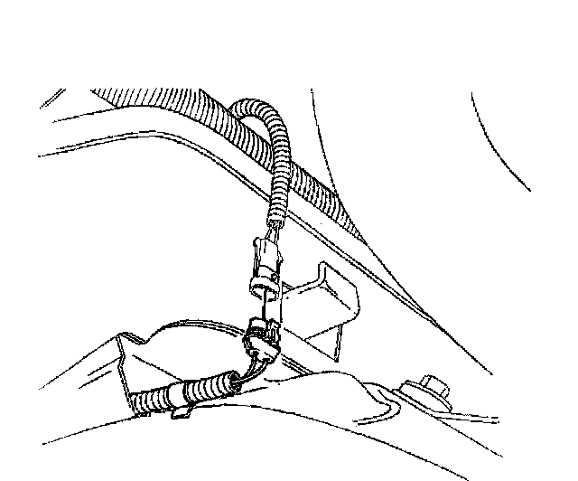
26. Disconnect the wheel speed sensors electrical connectors.
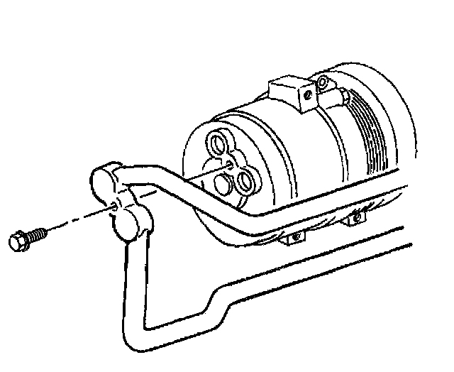
27. Remove the air conditioning (A/C) compressor and condenser hose bolt.
28. Discard the O-ring.
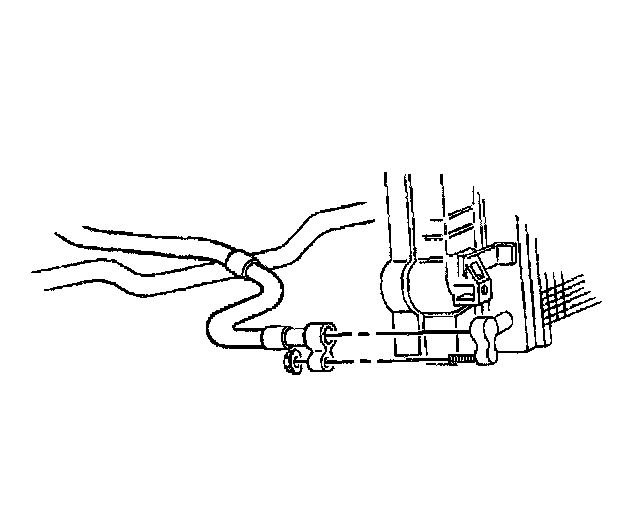
29. Remove the A/C compressor and condenser hose nut at the condenser.
30. Discard the O-ring.
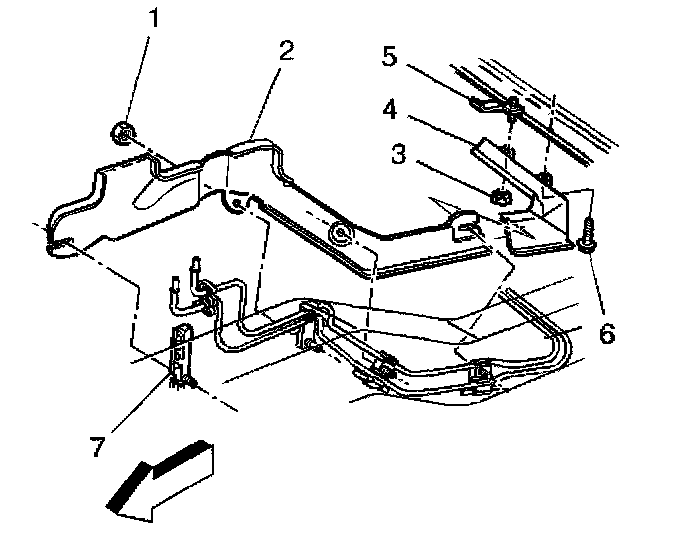
31. Remove the front fuel pipe heat shield nuts (1).
32. Remove the front fuel pipe heat shield (2).
33. Disconnect the brake lines from the brake pipe clip.
34. Lower the vehicle.
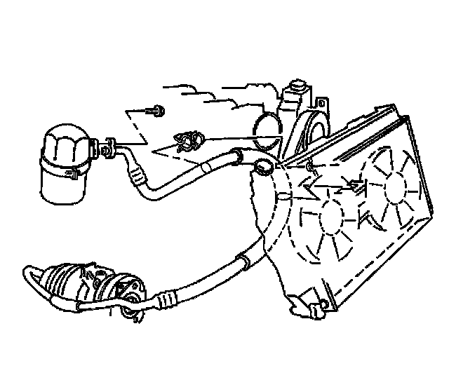
35. Remove the A/C compressor and condenser hose bolt at the accumulator.
36. Discard the O-ring.
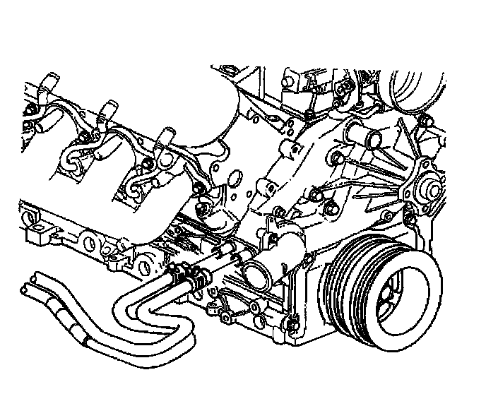
37. Remove the inlet and outlet heater hoses from the water pump.
37.1. Squeeze the hose clamp together with pliers.
37.2. Slide the hose clamp away from the water pump fitting.
37.3. Gently twist and pull the heater hose from the water pump fitting.
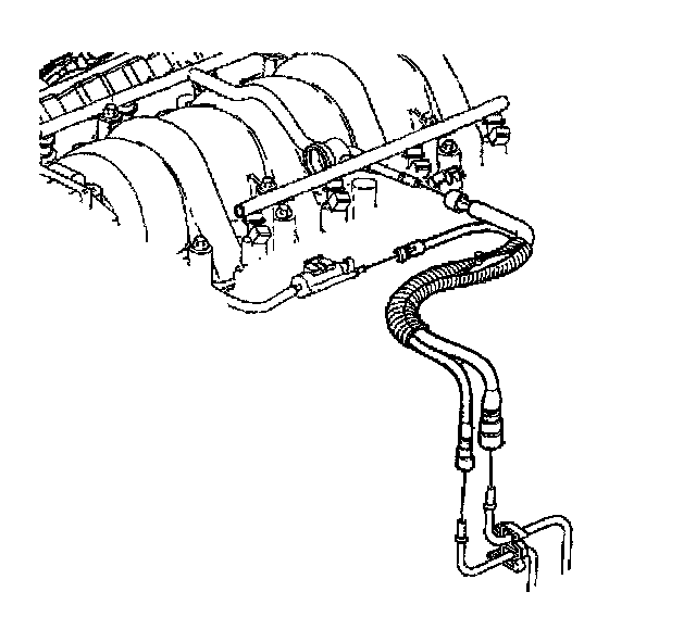
38. Disconnect the fuel feed pipe from the fuel rail.
39. Disconnect the fuel return pipe from the fuel rail.
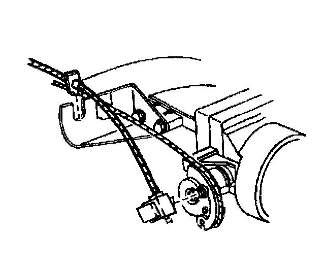
40. Remove the cruise control cable from the throttle lever.
CAUTION: In order to avoid possible injury or vehicle damage, always replace the accelerator control cable with a NEW cable whenever you remove the engine from the vehicle.
In order to avoid cruise control cable damage, position the cable out of the way while you remove or install the engine. Do not pry or lean against the cruise control cable and do not kink the cable. You must replace a damaged cable.
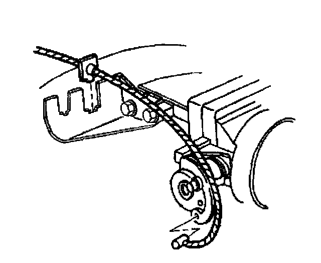
41. Remove the accelerator control cable from the throttle lever.
42. Unsnap and remove the accelerator and cruise control cable from the throttle body bracket.
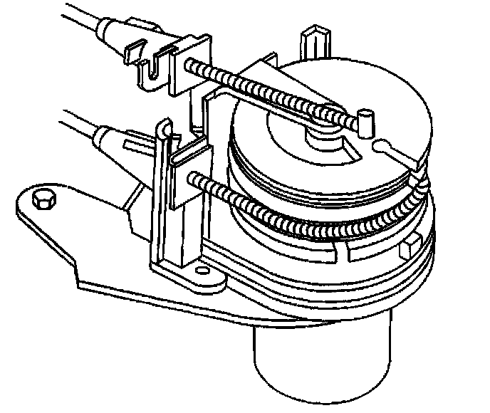
43. Remove the cruise control and accelerator control cables from the servo adjuster, if equipped.
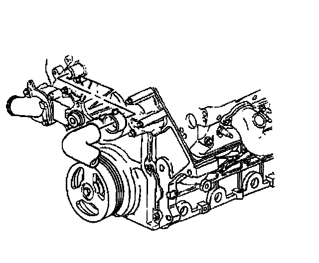
44. Remove the inlet hose from the water pump.
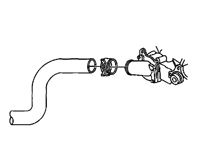
45. Remove the outlet hose from the water outlet.
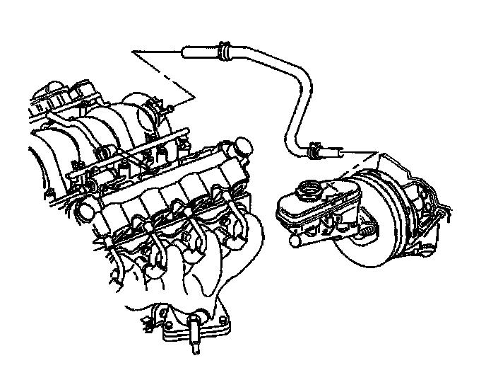
46. Remove the brake booster vacuum hose.
47. Remove the front two brake pipes from the brake pressure modulator valve.
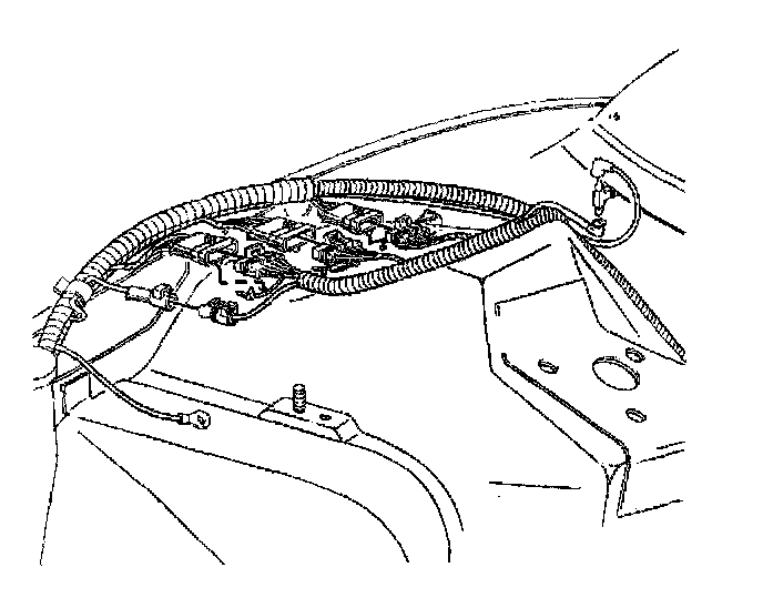
48. Disconnect the secondary captured locks.
49. Disconnect the forward lamp harness from the engine harness.
50. Disconnect the engine harness vacuum tube from the bottom of the vacuum check valve.
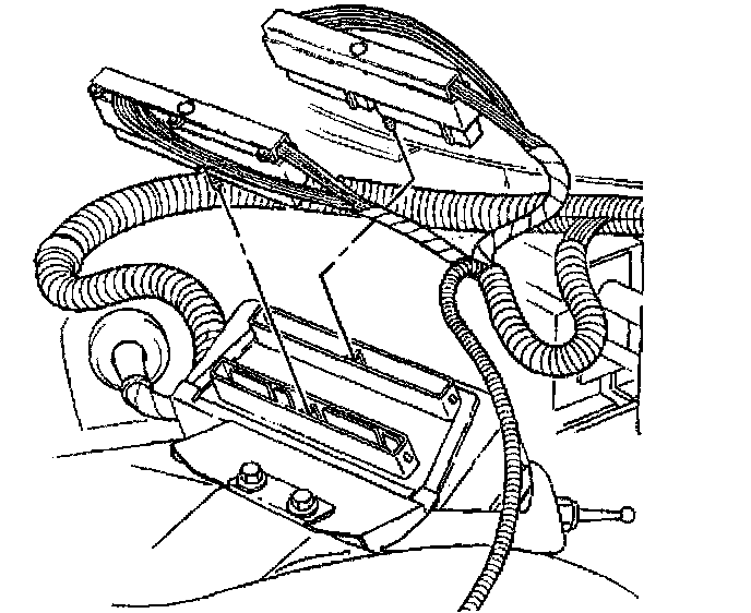
51. Disconnect the Powertrain Control Module (PCM) connectors.
52. Remove the PCM from the vehicle.
53. Remove the right side insulator panel.
54. Remove the hinge pillar trim panel.
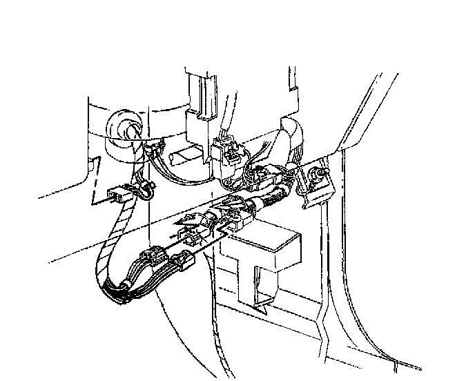
55. Disconnect the engine wiring harness from the instrument panel wiring harness.
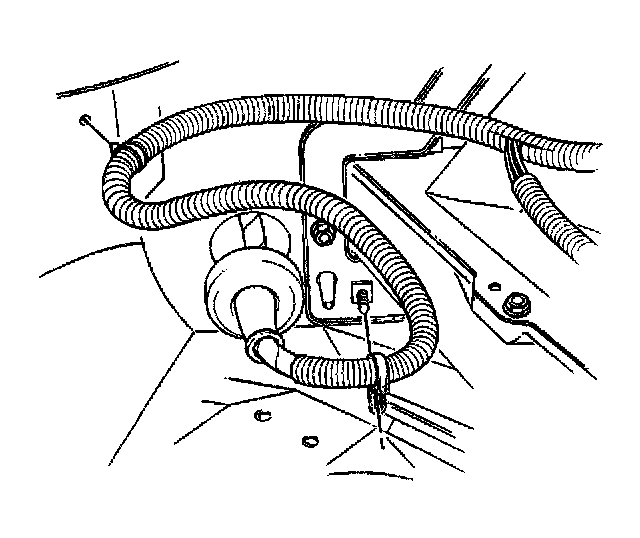
56. Remove the engine wire harness through the front of dash. Place the harness on top of the engine.
57. Remove the floor shift control, if equipped.
58. Remove the transmission control, if equipped.
59. Raise and suitably support the vehicle.
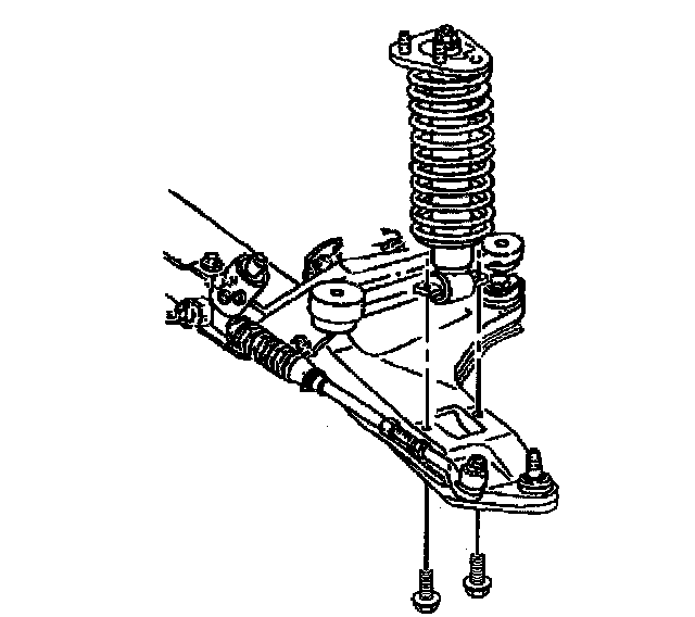
60. Remove the right and left lower shock bolts from the lower control arms.
61. Remove the cotter pins and nuts from the left and right upper ball joints.
62. Using J39549 separate the upper control arms from the steering knuckles.
63. Support both steering knuckles.
64. Position the J39580 below the vehicle.
65. Lower the vehicle.
66. Lay the engine wire harness on top of the engine.
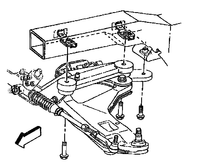
67. Remove the front crossmember bolts.
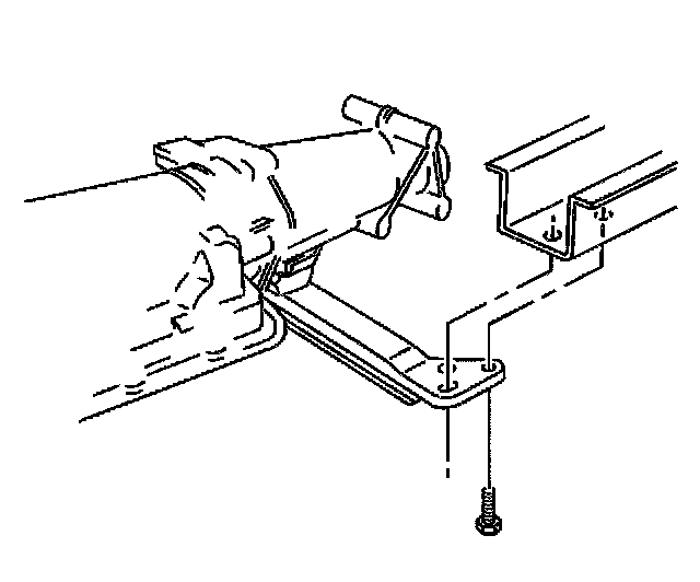
68. Remove the transmission support bolts.
69. Raise the vehicle and remove the engine and transmission from the vehicle.
70. Secure the crossmember to the J39580.
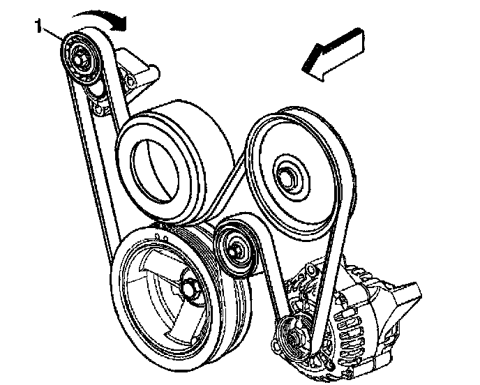
71. Position a hex-head socket on the belt tensioner pulley (1) bolt.
72. Rotate the drive belt tensioner clockwise to relieve the tension on the drive belt.
73. Remove the drive belt from the tensioner and pulleys.
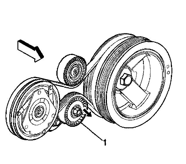
74. Position a hex-head socket on the belt tensioner pulley (1) bolt.
75. Rotate the air conditioning (A/C) drive belt tensioner clockwise to relieve the tension on the drive belt.
76. Remove the A/C drive belt from the crankshaft balancer and A/C compressor.

77. Disconnect the A/C compressor electrical connector.
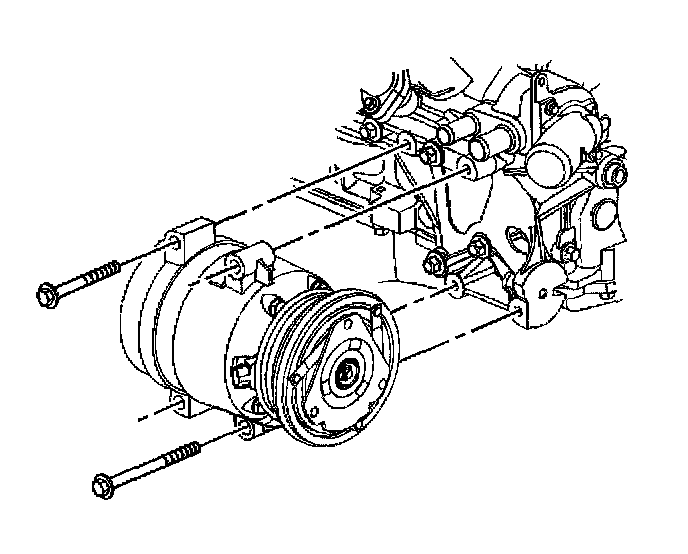
78. Remove the A/C compressor bolts.
79. Remove the A/C compressor.
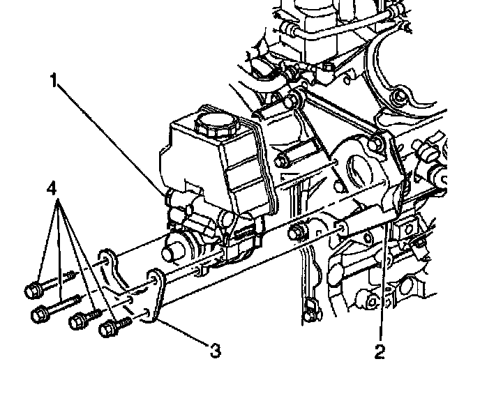
80. Remove the power steering pump bolts (4) and pump brace (3).
81. Remove the power steering pump (1) from the bracket (2).
82. Reposition the power steering pump to the crossmember.
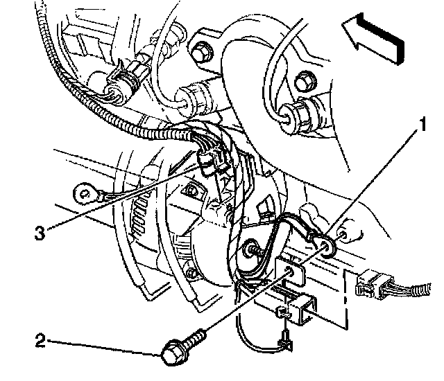
83. Disconnect the generator electrical connector (3)
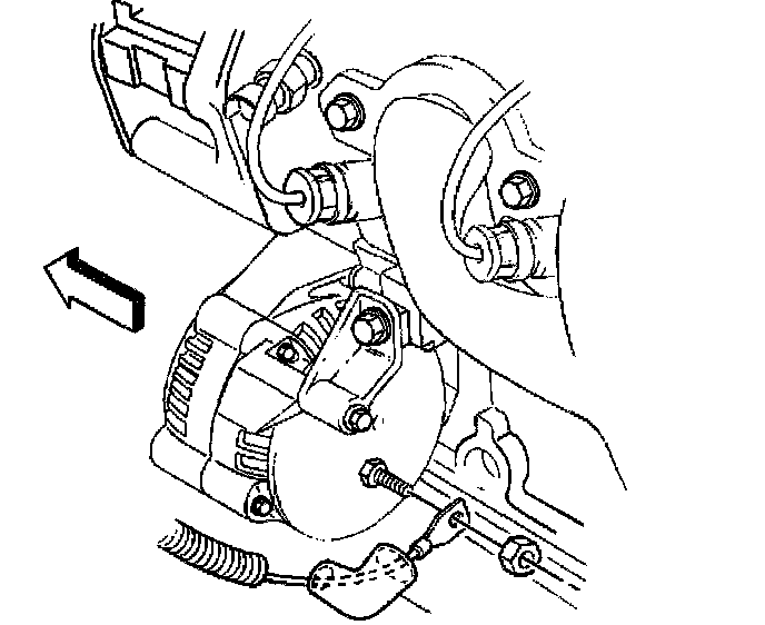
84. Remove the positive cable nut from the generator.
85. Remove the positive cable from the generator.
86. Install a lifting device to the engine
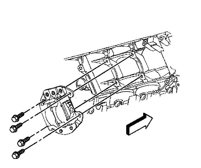
87. Remove the right side engine mount bracket to block bolts and bracket.
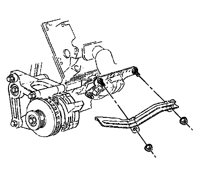
88. Remove the engine mount heat shield nuts.
89. Remove the engine mount heat shield.
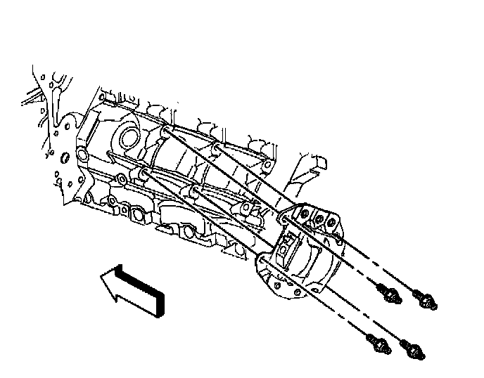
90. Remove the left side engine mount bracket to block studs and bracket.
91. With the aide of an assistant, raise the engine and transmission from the crossmember.
92. Disconnect the electrical connectors from the transmission.
93. If equipped with an automatic transmission perform the following:
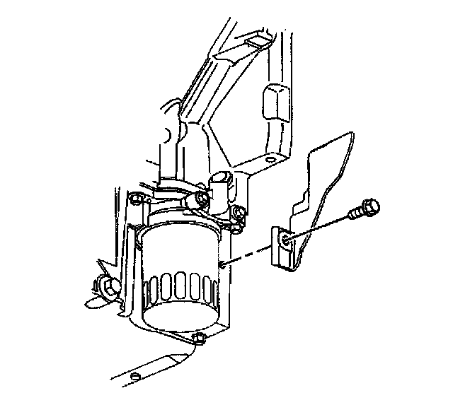
94. Remove the left side transmission closeout and bolt.
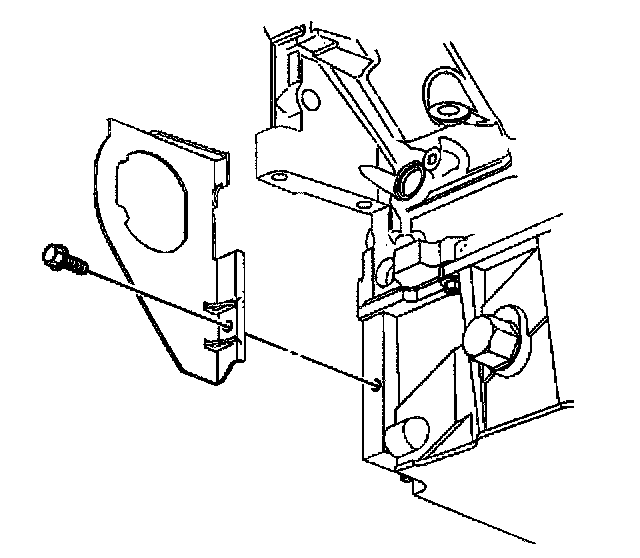
95. Remove the right side transmission closeout and bolt.
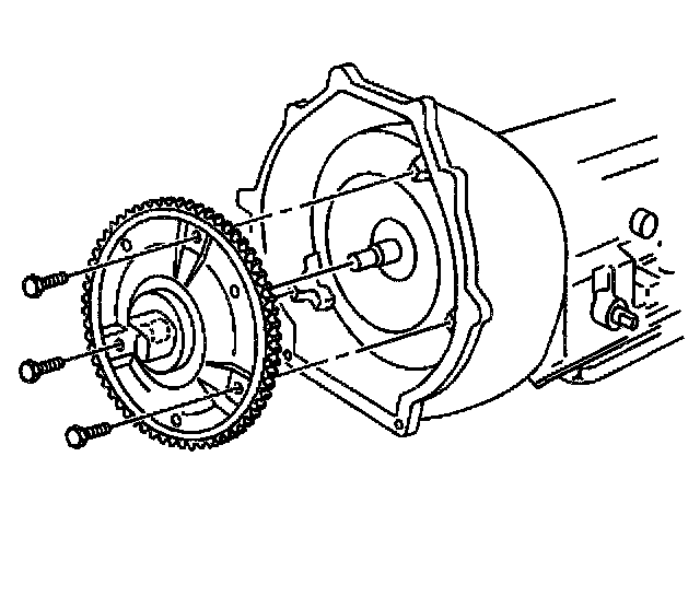
96. Remove the flywheel to torque converter bolts.
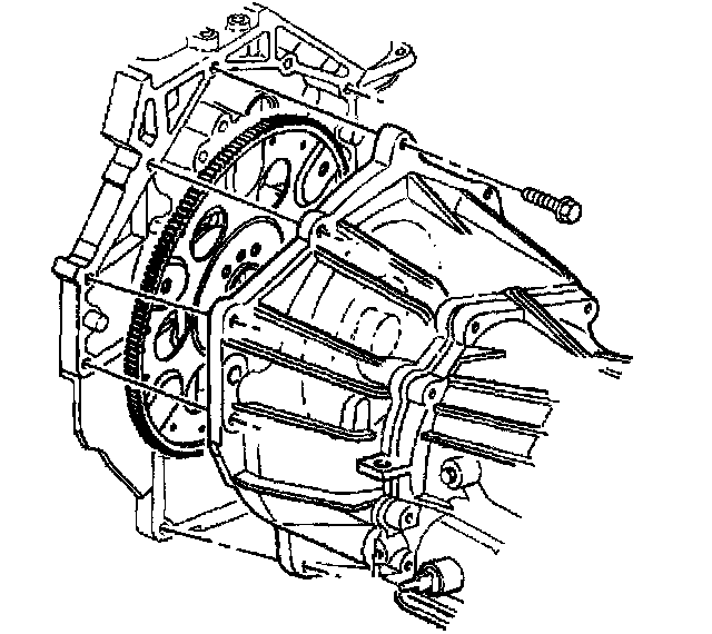
97. Remove the transmission to engine bolts.
98. Separate the transmission from the engine.
99. Attach the J21366 to the transmission.
100. If equipped with a manual transmission perform the following:
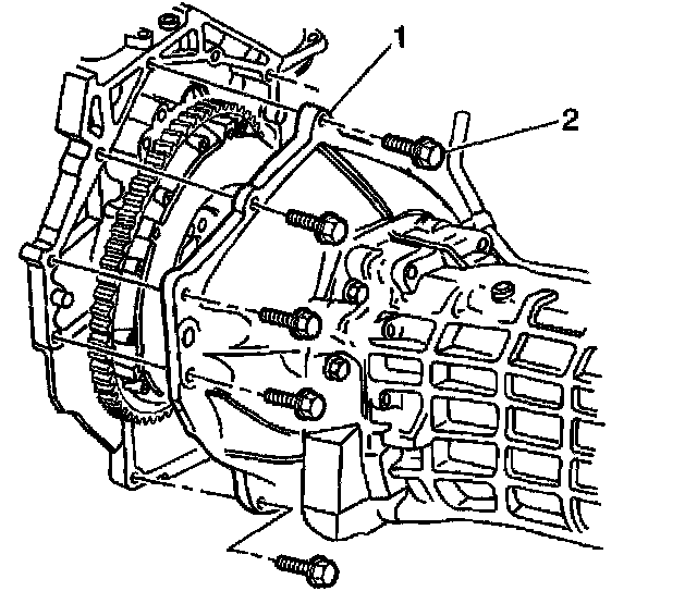
101. Remove the flywheel housing to engine bolts (2).
102. Separate the flywheel housing from the engine.
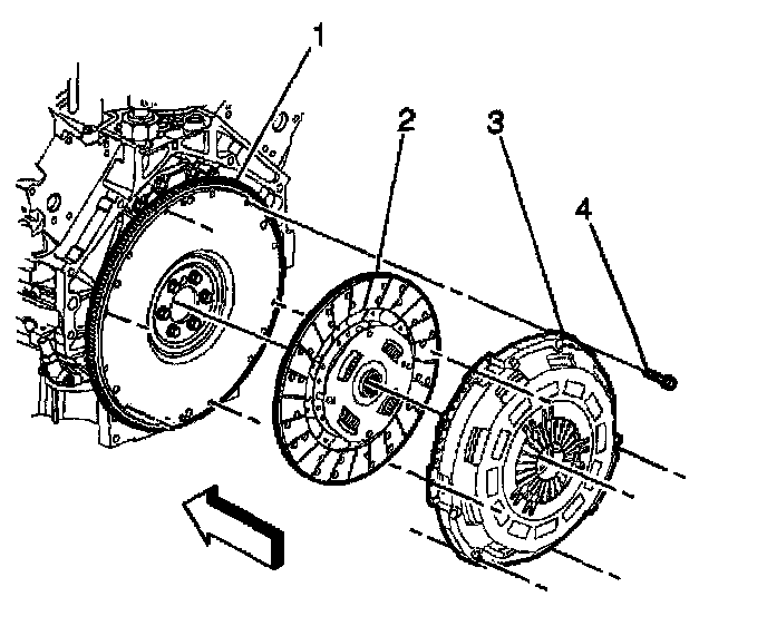
103. Remove the pressure plate bolts (4).
104. Remove the pressure plate (3) and clutch disc (2) from the flywheel (1).
105. Install the engine to a engine stand.
106. Remove the engine lifting devise.