Crank & Bearings Clean & Inspect (Measure Main BRG. Clearance)
CRANKSHAFT AND BEARINGS CLEAN AND INSPECT (MEASURING MAIN BRG CLEARANCE)MEASURING MAIN BEARING CLEARANCE
IMPORTANT: The crankshaft main bearings are a precision insert type. Main bearing caps are machined with the engine block for proper clearance and cannot be shimmed or filed for bearing fit. If the clearances are found to be excessive, new bearings and/or engine block and cap repair or replacement may be required.
Do not rotate the crankshaft while gauging plastic is between the crankshaft journal and the bearing surface.
The crankshaft bearing clearances are critical. Excessive bearing clearance may effect crankshaft position sensor signals and may effect On-Board Diagnostics (OBD II) system operation.
^ Tools Required
- J41818 Crankshaft Bearing Cap Remover
- J6125-1B Slide Hammer
- J36660 Torque Angle Meter
IMPORTANT: Remove the bearing cap side bolts prior to cap removal.
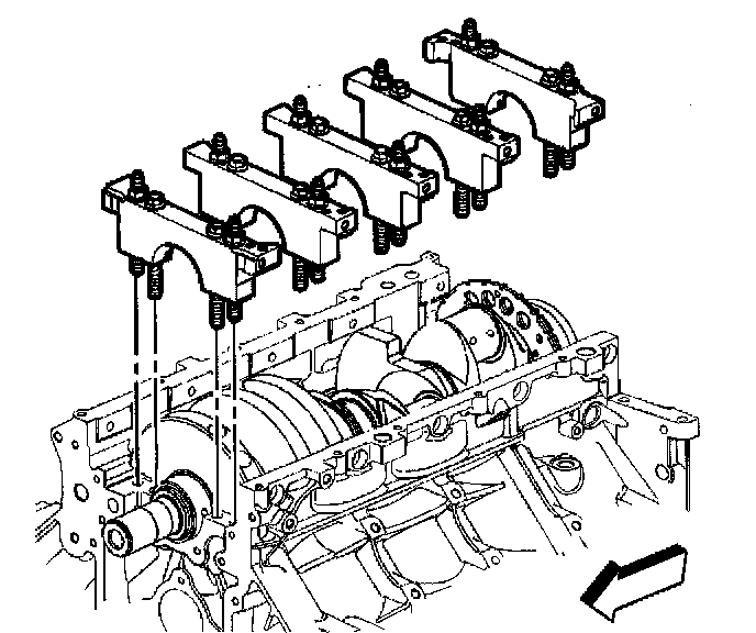
1. Remove the bearing cap M8 side bolts.
2. Remove the bearing cap M10 bolts and studs.
NOTICE: Refer to Fastener Notice in Service Precautions.
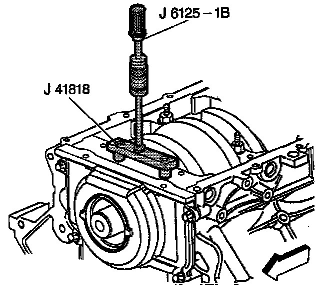
3. Install the J41818 to the bearing cap.
^ Tighten the J41818 bolts to 11 Nm (100 inch lbs.).
4. Install the J6125-1B to the J41818 in order to remove the bearing cap.
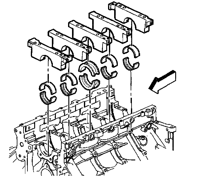
5. Remove the bearing cap and lower bearing.
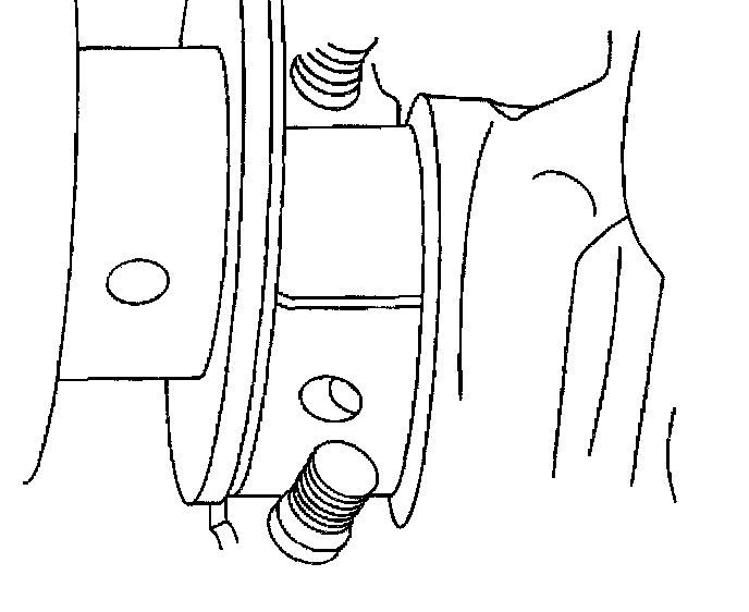
6. Install gauging plastic onto the crankshaft journal. Install the gauging plastic the full width of crankshaft bearing journal.
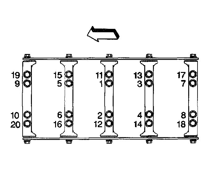
7. Install the bearing, bearing cap, bolts and studs.
7.1. Tighten the inner bolts (1-10) a first pass in sequence to 20 Nm (15 ft. lbs.).
7.2. Tighten the inner bolts (1-10) a final pass in sequence to 80 degrees using the J36660.
7.3. Tighten the outer studs (11-20) a first pass in sequence to 20 Nm (15 ft. lbs.).
7.4. Tighten the outer studs (11-20) a final pass in sequence to 53 degrees using the J36660.
7.5. Tighten the side cap bolts to 25 Nm (18 ft. lbs.).
Tighten the bolt on one side of the bearing cap and then tighten the bolt on the opposite side of the same bearing cap.
IMPORTANT: Remove the bearing cap side bolts prior to cap removal.
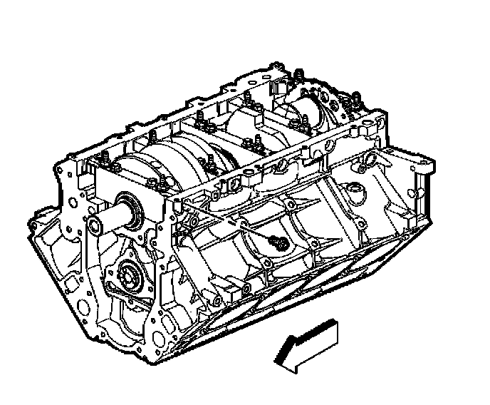
8. Remove the bearing cap M8 side bolts.
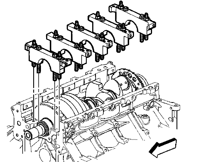
9. Remove the bearing cap bolts and studs.
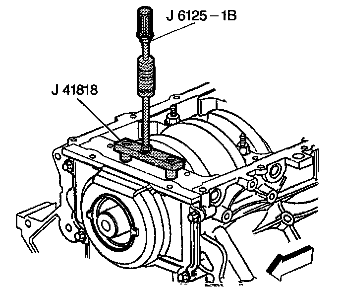
10. Use the J41818 and the J6125-1B in order to remove the bearing cap.
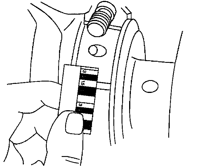
11. Measure the gauging plastic at its widest area using the scale supplied with the plastic gauging kit.
^ If the gauging plastic shows irregularity in the journal exceeding 0.025 mm (0.001 inch), remove the crankshaft and measure the journal with a micrometer.
^ If the bearing clearance is greater than 0.054 mm (0.00212 inch), select and install an undersized bearing set, and measure the clearance with gauging plastic.
^ If clearance cannot be brought to specifications, replace the crankshaft or grind the crankshaft for use with the next undersized bearing.
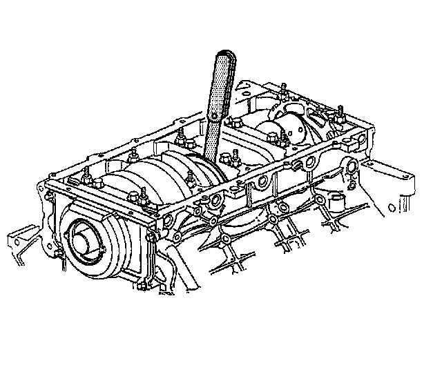
12. Measure the crankshaft end play.
12.1. Thrust the crankshaft forward or rearward.
12.2. Insert a feeler gauge between the center crankshaft bearing and the bearing surface of the crankshaft and measure the bearing clearance.
The proper crankshaft end play clearance is 0.04 - 0.2 mm (0.0015 - 0.0078 inch).
12.3. If the bearing clearance is not within specifications:
^ Inspect the thrust surfaces for nicks, gouges or raised metal. Minor imperfections may be removed with a fine stone.
^ Replace the thrust bearings and measure the end play.
^ If the correct measurements cannot be obtained, repair the crankshaft thrust surfaces or replace the crankshaft.