Vacuum Brake Booster Replacement
REMOVAL PROCEDURE1. Remove the hood rear seal.
2. Remove the air inlet screen.
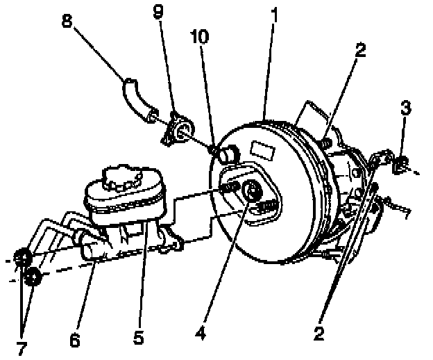
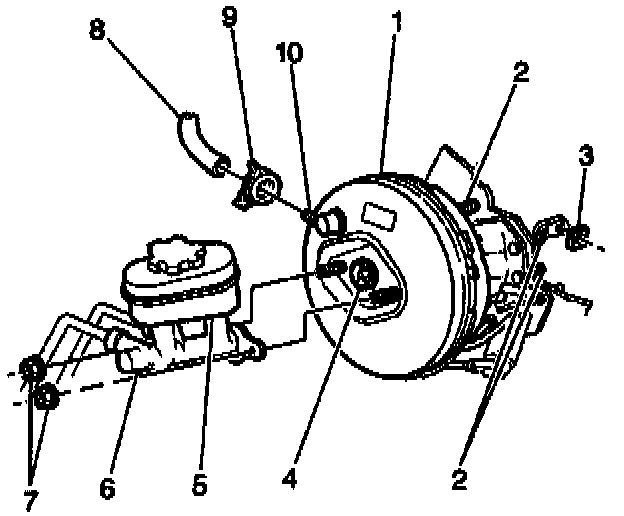
3. Remove the brake booster vacuum hose clamp (9) and the vacuum hose (8) from the check valve (4).
4. Remove the master cylinder nuts (7) attaching the master cylinder (6) to the brake booster (1).
5. Remove the master cylinder from the brake booster.
^ Move the master cylinder forward and toward the driver's side in order to provide clearance for the booster. Moving the master cylinder will flex the brake pipes slightly.
^ Do not bend or distort the brake pipes.
6. Remove the left side instrument panel insulator. Refer to Instrument Panel Insulator in Instrument Panel, Gauges and Warning Indicators.
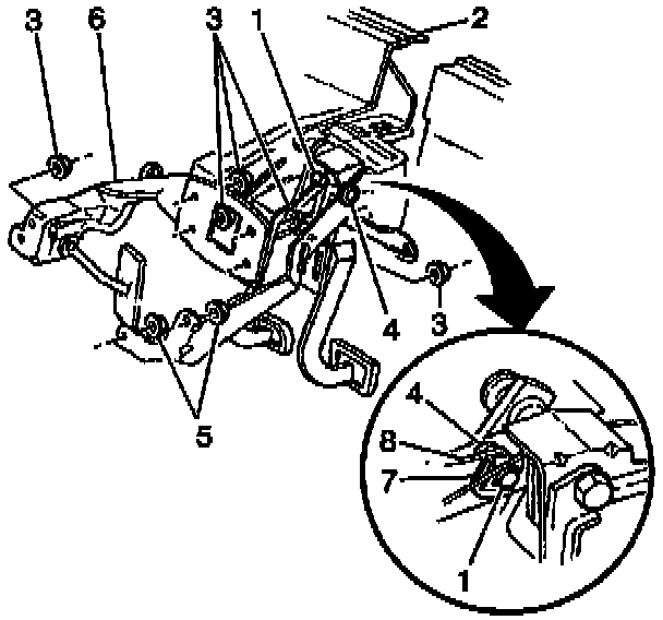
7. Remove the brake pedal nuts (3) attaching the brake booster to the brake pedal with bracket (6).
8. On vehicles equipped with manual transmissions, loosen the clutch master cylinder nuts (5).
9. Remove the brake booster pushrod (8) from the brake pedal lever pin.
^ From inside the vehicle, remove the brake pedal pushrod retainer (7) and the pushrod washer (4).
^ Tilt the entire brake booster slightly in order to work the brake booster pushrod (8) off the brake pedal pin. Do no put undue side pressure on the pushrod.
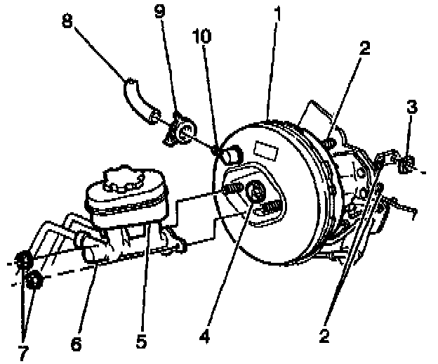
10. Remove the power brake booster (1) from the vehicle.
INSTALLATION PROCEDURE
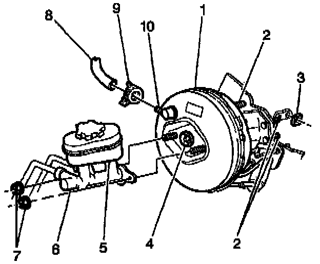
1. Install the power brake booster (1) onto the vehicle.
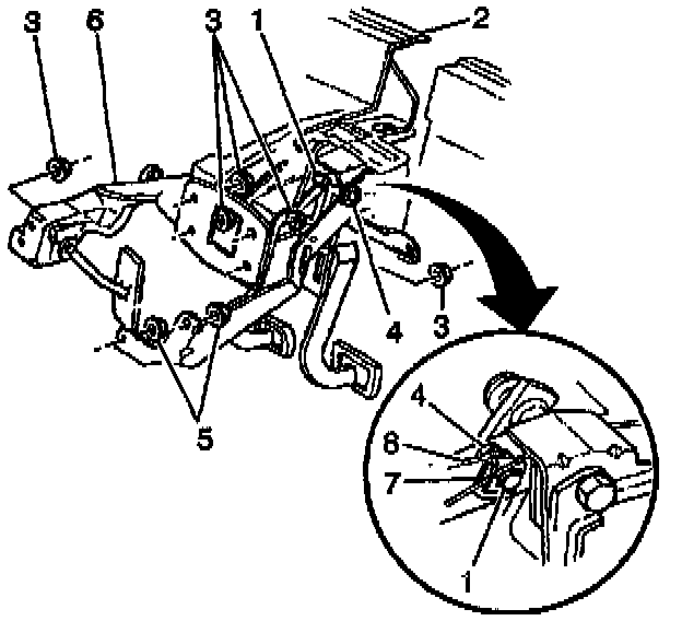
2. Install the brake booster pushrod (8) onto the brake pedal lever pin (1).
^ Tilt the entire brake booster slightly in order to work the brake booster pushrod (8) onto the brake pedal pin. Do not put undue side pressure on the pushrod.
^ From inside the vehicle, install the brake pedal pushrod washer (4) and the pushrod retainer (7).
NOTICE: Always use the correct fastener in the proper location. When you replace a fastener, use ONLY the exact part number for that application. The manufacturer will call out those fasteners that require a replacement after removal. The manufacturer will also call out the fasteners that require thread lockers or thread sealant. UNLESS OTHERWISE SPECIFIED, do not use supplemental coatings (paints, greases, or other corrosion inhibitors) on threaded fasteners or fastener joint interfaces. Generally, such coatings adversely affect the fastener torque and joint clamping force, and may damage the fastener. When you install fasteners, use the correct tightening sequence and specifications. Following these instructions can help you avoid damage to parts and systems.
3. Install the brake pedal nuts.
Tighten the brake pedal nuts to 20 Nm (15 ft. lbs.) in the following sequence:
3.1. Inboard upper
3.2. Outboard lower
3.3. Outboard upper
3.4. Inboard lower
4. On vehicles equipped with manual transmissions, tighten the clutch master cylinder nuts (5).
Tighten the clutch master cylinder nuts to 27 Nm (20 ft. lbs.).
5. Install the master cylinder (6) onto the brake booster (1).
6. Install the master cylinder nuts attaching the master cylinder to the brake booster.
Tighten the brake master cylinder nuts to 29 Nm (21 ft. lbs.).
7. Connect the vacuum hose (8) and the clamp (9) to the check valve (10).
8. Install the left hand instrument panel insulator. Refer to Instrument Panel Insulator in Instrument Panel, Gauges and Warning Indicators.
9. Install the transmission fluid filler tube.
10. Install the air inlet screens.