Parking Brake Lever: Service and Repair
REMOVAL PROCEDURENotice: Do not lubricate the parking brake cables. Lubrication may damage the plastic coating on the parking brake cables.
If the park brake lever does not fully return, lubricate the following parts using chassis lubricant or the equivalent:
^ The adjust pawl pin
^ The handle ratchet
^ The adjusting ratchet
^ Tools Required
- J 37043 Parking Brake Cable Release Tool
1. Remove the front floor console. Refer to Instrument Panel, Gages and Warning Indicators.
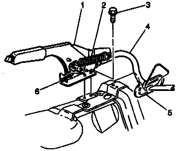
2. Disconnect the electrical connector from the park brake indicator switch (6).
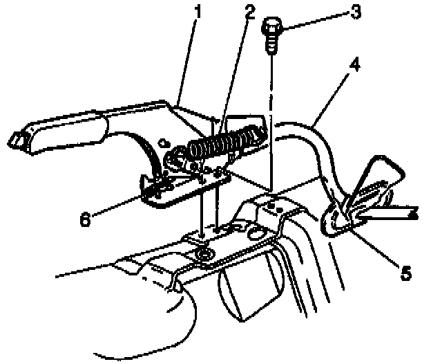
3. Remove the park brake indicator switch screw and the park brake indicator switch (6) from the park brake lever (1).
4. With the park brake lever (1) in the up position, remove the park brake lever spring (2).
5. With the park brake lever (1) in the down position, rotate the adjuster arm toward the front of the vehicle until a 3 mm metal pin can be inserted into the hole.
5.1. Remove and discard the remaining piece of plastic shear pin.
5.2. Insert a 3 mm metal pin into the hole, locking out the self adjuster.
6. Raise and suitably support the vehicle.
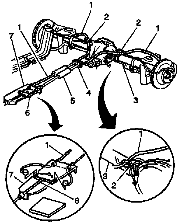
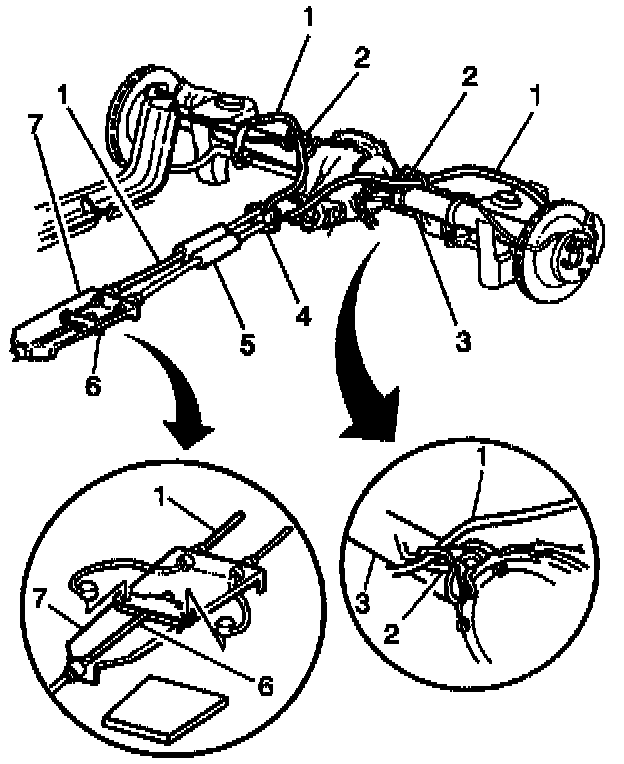
7. Remove the rear cables from the park brake cable equalizer (6).
8. Lower the vehicle.
9. Bend back the cable retainer tab on the pulley.
10. Remove the barrel-shaped front cable end fitting from the adjuster track on the pulley.
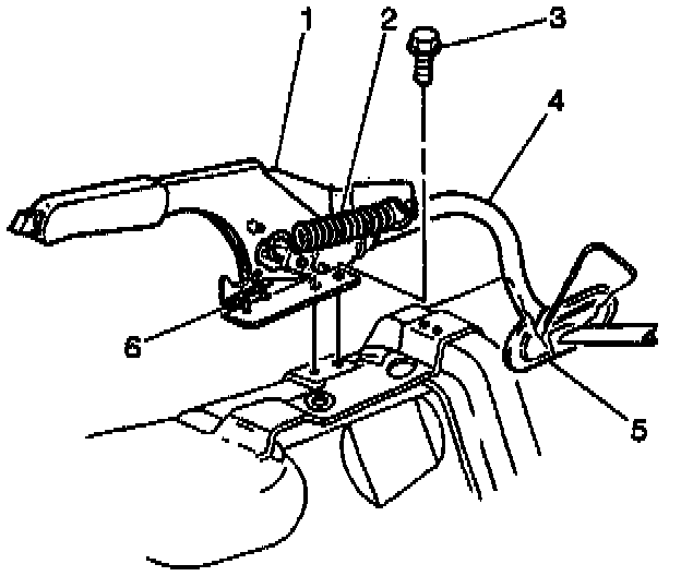
11. Remove the park brake lever bolts (3) and the park brake lever (1) from the floor pan.
12. Use the J 37043 in order to remove the park brake front cable (4) from the park brake lever (1).
INSTALLATION PROCEDURE
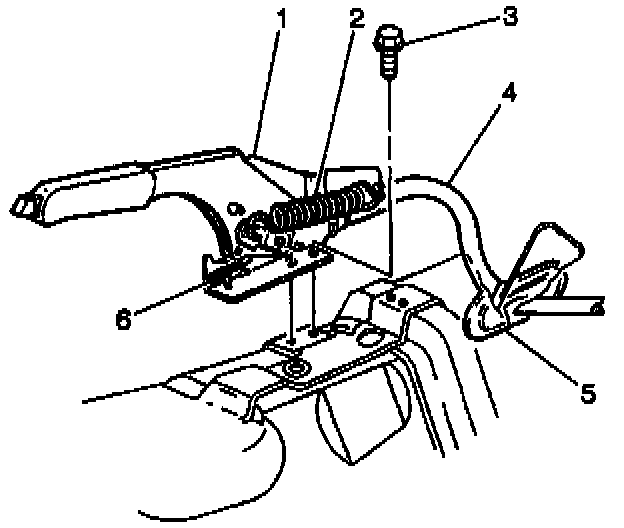
1. Connect the park brake front cable (4) to the park brake lever (1).
NOTICE: Always use the correct fastener in the proper location. When you replace a fastener, use ONLY the exact part number for that application. The manufacturer will call out those fasteners that require a replacement after removal. The manufacturer will also call out the fasteners that require thread lockers or thread sealant. UNLESS OTHERWISE SPECIFIED, do not use supplemental coatings (paints, greases, or other corrosion inhibitors) on threaded fasteners or fastener joint interfaces. Generally, such coatings adversely affect the fastener torque and joint clamping force, and may damage the fastener. When you install fasteners, use the correct tightening sequence and specifications. Following these instructions can help you avoid damage to parts and systems.
2. Connect the park brake lever (1) and the park brake lever bolts (3) to the floor pan.
Tighten the park brake lever bolts (3) to 12 Nm (106 inch lbs.).
3. Connect the park brake indicator switch screw and the park brake indicator switch (6) to the park brake lever (1).
Tighten the park brake indicator switch screw to 2.8 Nm (25 inch lbs.).
4. Connect the electrical connector to the park brake indicator switch (6).
5. Connect the barrel-shaped front cable end fitting to the adjuster track on the pulley.
6. Bend the cable retainer tab to the original position on the pulley.
7. If the rear cables were not disconnected from the equalizer, skip to step 11.
8. Raise the vehicle. Suitably support the vehicle.
9. Connect the rear cables to the equalizer (6).
10. Lower the vehicle.
11. Rotate the adjuster arm toward the rear of the vehicle and completely raise the park brake lever (1).
12. Install the park brake spring (2).
13. Remove the 3 mm metal pin from the hole.
14. Cycle the park brake lever three times.
15. Install the front floor console. Refer to Instrument Panel, Gauges and Warning Indicators.