P0803
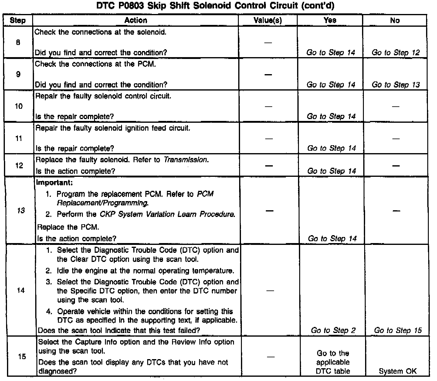
Diagnostic Chart:
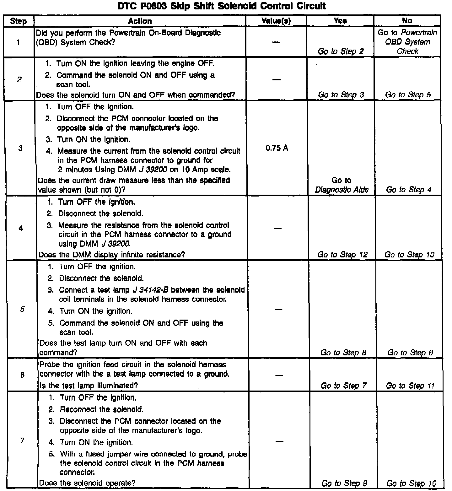
Diagnostic Chart:
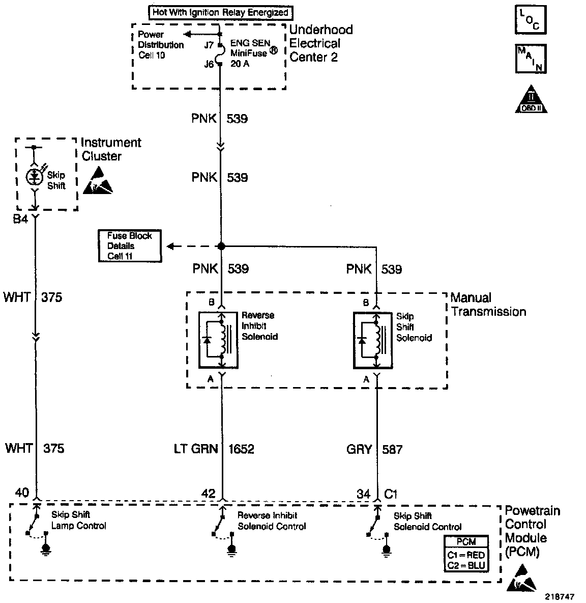
Wiring Diagram:
CIRCUIT DESCRIPTION
The ENG SEN mini fuse supplies an ignition voltage directly to the Skip Shift solenoid coil. The PCM controls the solenoid by grounding the control circuit via an internal switch called a driver. The driver supplies the ground for the component being controlled. Each driver has a fault line which the PCM monitors. When the PCM commands a component ON, the voltage of the control circuit should be low (near 0 volts). When the PCM commands the control circuit to a component OFF, the voltage potential of the circuit should be high (near battery voltage). If the fault detection circuit senses a voltage other than what is expected, the fault line status changes causing the DTC to set.
CONDITIONS FOR RUNNING THE DTC
- The engine speed is greater than 600 RPM.
- Ignition voltage greater than 6.0 volts but less than 16 volts.
CONDITIONS FOR SETTING THE DTC
- The PCM detects that the commanded state of the driver and the actual state of the control circuit do not match.
- All conditions exist for a minimum of 10 seconds.
ACTION TAKEN WHEN THE DTC SETS
- The PCM illuminates the Malfunction Indicator Lamp on the second consecutive drive trip that the diagnostic runs and fails.
- The PCM records the operating conditions at the time the diagnostic fails. The first time the diagnostic fails, the PCM stores this information in the Failure Records. If the diagnostic reports a failure on the second consecutive drive trip, the PCM records the operating conditions at the time of the failure. The PCM writes the conditions to the Freeze Frame and updates the Failure records.
CONDITIONS FOR CLEARING THE MIL/DTC
- A History DTC will clear after forty consecutive warm-up cycles, if no failures are reported by this or any other non-emission related diagnostic.
- A last test failed (Current DTC) will clear when the diagnostic runs and does not fail.
- The PCM battery voltage is interrupted.
- Use a scan tool in order to clear the MIL/DTC.
DIAGNOSTIC AIDS
- Using Freeze Frame and/or Failure Records data may aid in locating an intermittent condition. If you cannot duplicate the DTC, the information included in the Freeze Frame and/or Failure Records data can aid in determining how many miles since the DTC set. The Fail Counter and Pass Counter can also aid determining how many ignition cycles the diagnostic reported a pass and/or a fail. Operate the vehicle within the same freeze frame conditions (RPM, load, vehicle speed, temperature etc.) that you observed. This will isolate when the DTC failed.
- For an intermittent, refer to Symptoms. Testing and Inspection
TEST DESCRIPTION
The numbers below refer to the step numbers on the diagnostic table.
2. Listen for an audible click when the solenoid operates. Command both the ON and the OFF states. Repeat the commands as necessary.
3. This check detects a partially shorted coil which would cause excessive current flow. Leaving the circuit energized for 2 minutes allows the coil to warm up. When warm the coil may open (Amps drop to 0), or short (goes above 0.75 Amp).
5. Identify and test the solenoid coil terminals in order to avoid improper diagnosis.
13. If you do not find any trouble in the control circuit or the connection at the PCM, the PCM may be faulty. However, this is an extremely unlikely failure.