P0500
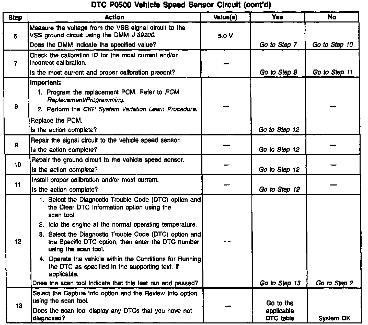
Diagnostic Chart:
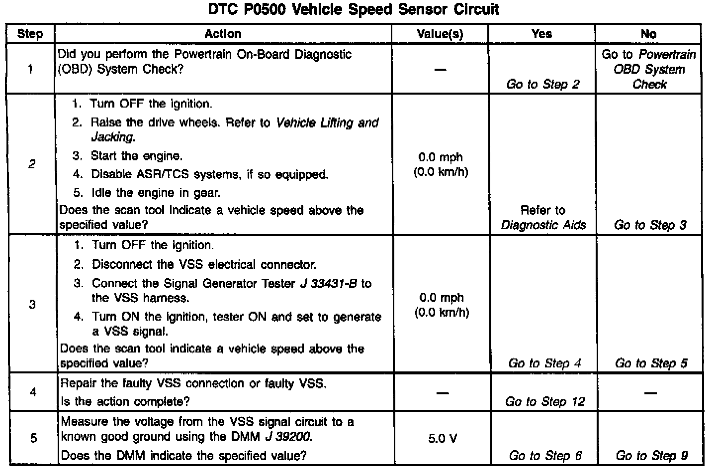
Diagnostic Chart:
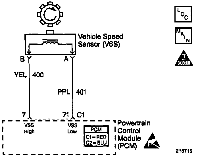
Wiring Diagram:
CIRCUIT DESCRIPTION
A toothed wheel mounted on the output shaft of the transmission generates an AC voltage pulse as it moves past the Vehicle Speed Sensor (VSS). The VSS contains a permanent magnet surrounded by a coil of wire, which produces a magnetic field. The toothed wheel interrupts the magnetic field this generates an AC voltage pulse. As the vehicle speed increases the AC voltage pulse rate also increases.
CONDITIONS FOR RUNNING THE DTC
- DTCs P0107, P0108, P0117, P0118, P0121, P0122, P0123, P0125, P0506, P0507 are not set.
- The engine coolant temperature is greater than 35°C (95°F).
- The engine speed is greater than 1000 RPM.
- The TP sensor angle is between 5.0% and 100%.
- The MAP is between 40 kPa and 100 kPa when the A/C is OFF.
- The MAP is between 45 kPa and 100 kPa when the A/C is ON.
- All conditions met for 2 seconds.
CONDITIONS FOR SETTING THE DTC
The PCM detects vehicle speed at 0 km/h (0 mph) for 100 seconds.
ACTION TAKEN WHEN THE DTC SETS
- The PCM illuminates the Malfunction Indicator Lamp on the second consecutive drive trip that the diagnostic runs and fails.
- The PCM records the operating conditions at the time the diagnostic fails. The first time the diagnostic fails, the PCM stores this information in the Failure Records. If the diagnostic reports a failure on the second consecutive drive trip, the PCM records the operating conditions at the time of the failure. The PCM writes the conditions to the Freeze Frame and updates the Failure records.
CONDITIONS FOR CLEARING THE MIL/DTC
- The PCM turns the MIL OFF after three consecutive drive trips that the diagnostic runs and does not fail.
- A last test failed (current DTC) clears when the diagnostic runs and does not fail.
- A History DTC clears after forty consecutive warm-up cycles, if this or any other emission related diagnostic does not report any failures.
- The PCM battery voltage is interrupted. Use a scan tool in order to clear the MIL/DTC.
DIAGNOSTIC AIDS
Inspect all of the circuits to the PCM and the VSS. Inspect the terminal connections at the VSS harness connector and at the PCM harness connector. If all of the circuits and connections are OK, replace the PCM.
For an intermittent, refer to Symptoms. Testing and Inspection
TEST DESCRIPTION
The numbers below refer to the step numbers on the diagnostic table.
2. The ASR/TCS must be disabled when performing this step. Whenever the ignition key is cycled to the OFF position and then cycled back ON, the ASR/TCS system will default ON.