P0404
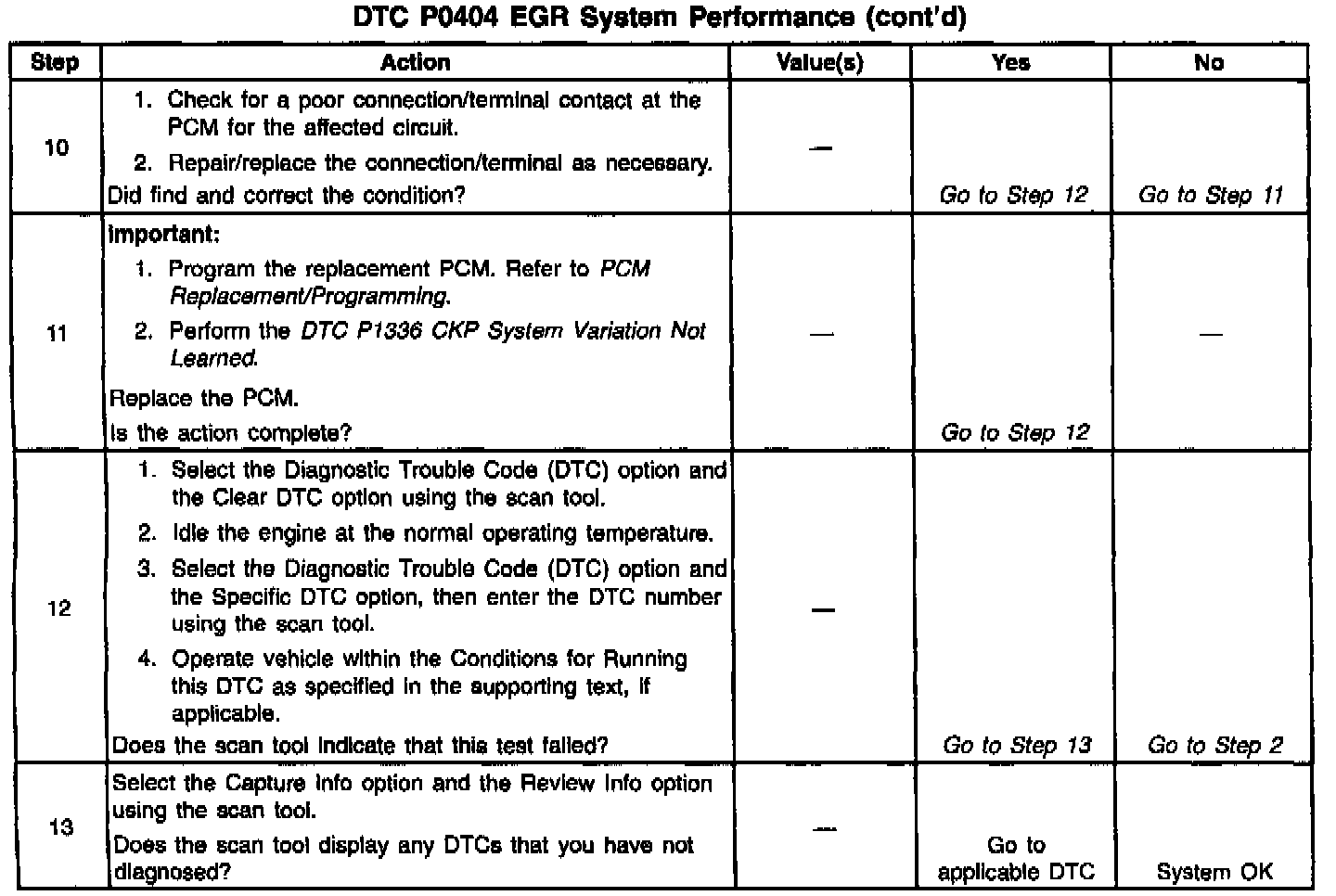
Diagnostic Chart:
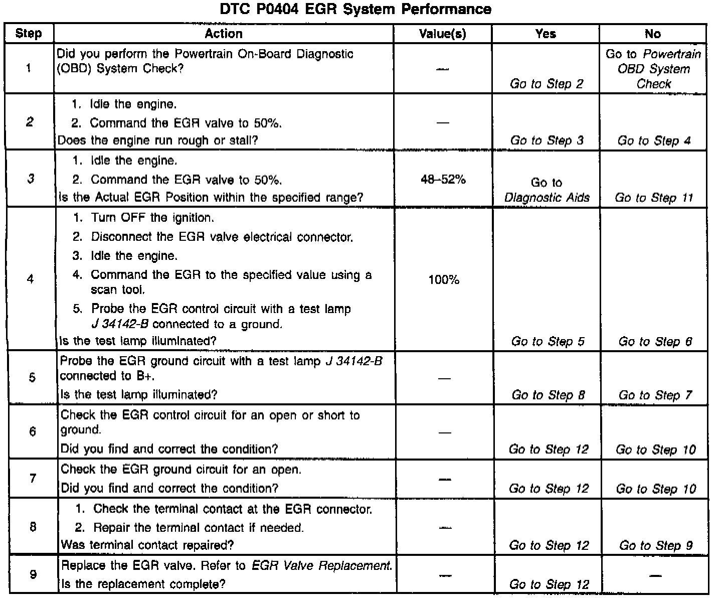
Diagnostic Chart:
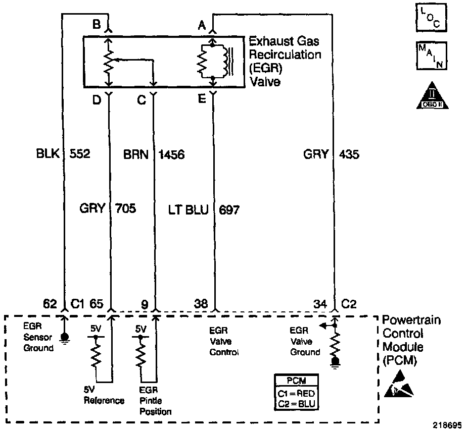
Wiring Diagram:
CIRCUIT DESCRIPTION
The ability of the PCM to control the EGR valve is checked with this test. The PCM calculates an error based on the difference between the actual EGR position and the desired EGR position. The PCM sets this DTC if the error is too great.
CONDITIONS FOR RUNNING THE DTC
- The ignition voltage is greater than 11.7 volts.
- The desired EGR position is greater than 0%.
CONDITIONS FOR SETTING THE DTC
- The difference between the desired EGR position and the actual EGR position is greater than 20%.
- The failure counter is greater than a predetermined value.
ACTION TAKEN WHEN THE DTC SETS
- The PCM disables the EGR for the ignition cycle.
- The PCM illuminates the Malfunction Indicator Lamp (MIL) when the diagnostic runs and fails.
- The PCM records the operating conditions at the time the diagnostic fails. The PCM stores this information in the Freeze Frame and/or the Failure Records.
CONDITIONS FOR CLEARING THE MIL/DTC
- The PCM turns the MIL OFF after three consecutive drive trips that the diagnostic runs and does not fail.
- A last test failed (current DTC) clears when the diagnostic runs and does not fail.
- A History DTC clears after forty consecutive warm-up cycles, if this or any other emission related diagnostic does not report any failures.
- The PCM battery voltage is interrupted.
- Use a scan tool in order to clear the MIL/DTC.
TEST DESCRIPTION
The numbers below refer to the step numbers on the Diagnostic Table.
2. This step determines if the EGR valve can be commanded open.
3. This step determines if the EGR valve can maintain the commanded EGR position.