P0327
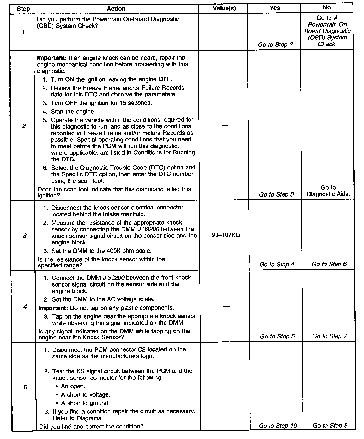
1 Of 2:
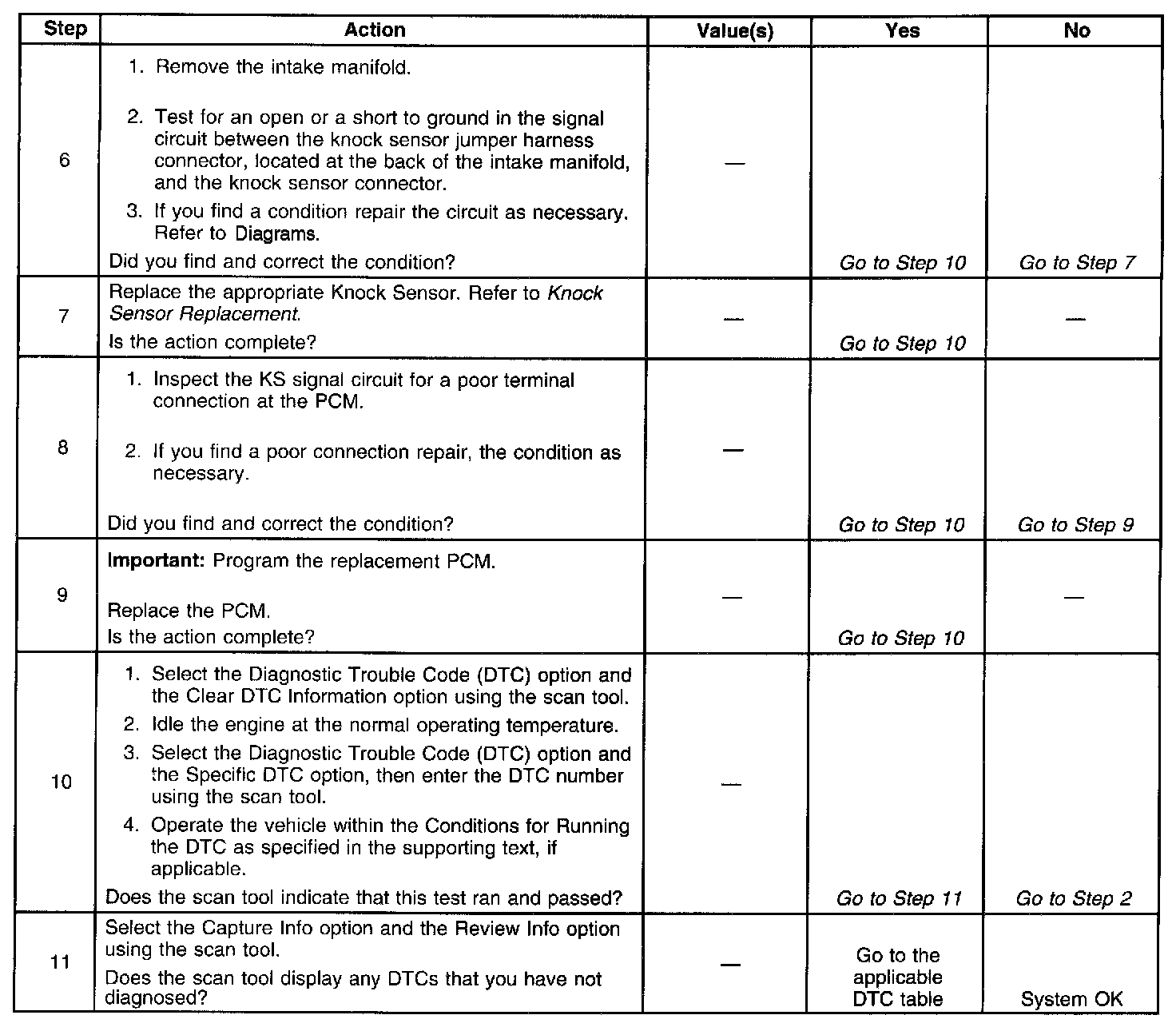
2 Of 2:
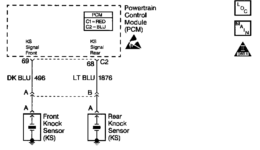
Circuit Description
The Knock Sensor (KS) system detects engine detonation. The PCM retards the spark timing based on the signals from the knock sensors. The knock sensors produce an AC voltage. The knock sensor voltages are an input to the PCM. The amount of AC voltage produces is proportional to the amount of knock.
An operating engine produces a normal amount of engine mechanical vibration (noise). The knock sensors produce an AC voltage signal from this noise. When an engine operates, the PCM learns the minimum and maximum frequency of the noise the engine produces. When the PCM determines that this frequency is less than or greater than the expected amount, a knock sensor DTC sets.
Conditions for Running the DTC
- The engine run time is greater than 20 seconds.
- The engine coolant temperature is greater than 70°C (158°F).
- The engine speed is between 1,500 and 3,500 RPM.
- The TP sensor angle is greater than 0.5%.
- The MAP sensor is less than 60 kPa.
Conditions for Setting the DTC
The PCM determines that this frequency is less than or greater than the expected amount for less than 3 seconds.
Action Taken When the DTC Sets
- The PCM illuminates the Malfunction Indicator Lamp on the second consecutive ignition cycle that the diagnostic runs and fails.
- The PCM records the operating conditions at the time the diagnostic fails. The first time the diagnostic fails, the PCM stores this information in the Failure Records. If the diagnostic reports a cycle, the PCM records the operating conditions at the time of the failure. The PCM writes the conditions to the Freeze Frame and updates the Failure records.
Conditions for Clearing the MIL/DTC
- The PCM turns the MIL OFF after three consecutive ignition cycles that the diagnostic runs and does not fail.
- A last test failed (current DTC) clears when the diagnostic runs and does not fail.
- A History DTC clears after forty consecutive warm-up cycles, if this or any other emission related diagnostic does not report any failures.
- Use a scan tool in order to clear the MIL/DTC.
Diagnostic Aids
Important:
- Remove any debris from the PCM connector surfaces before servicing the PCM. Inspect the PCM connector gaskets when diagnosing/replacing the PCM. Ensure that the gaskets are installed correctly. The gaskets prevent contaminate intrusion into the PCM.
- For any test that requires probing the PCM or a component harness connector, use the Connector Test Adapter Kit J 35616-A. Using this kit prevents damage to the harness connector terminals.
- Inspect the knock sensor for proper installation. A knock sensor that is loose or over torqued may cause the DTC P0327 to set.
- Using the Freeze Frame and/or Failure Records data may aid in locating an intermittent condition. If you cannot duplicate the DTC, the information included in the Freeze Frame and/or Failure Records data can help determine how many miles since the DTC set. The Fail Counter and Pass Counter can also help determine how many ignition cycles the diagnostic reported a pass and/or a tail. Operate the vehicle within the same freeze frame conditions (RPM, load, vehicle speed, temperature etc.) that you observed. This will isolate when the DTC failed.
- For an intermittent, refer to Symptoms.
Test Description
The numbers below refer to the step numbers on the diagnostic table.
2. This verifies the malfunction is present. The scan tool will display DTC Ran=Yes and Pass=Int if the failure is intermittent. This indicates the diagnostic passed this ignition cycle and failed this ignition cycle. At this point the resistance of the knock sensors should be verified to be in the correct range. It the knock sensor resistances are correct, inspect the KS system wiring connections. When inspecting the KS system connections, start at the KS system jumper harness connector located behind the intake manifold. Then inspect the connections at the PCM. Refer to the wiring schematic for the correct connector and terminal. Then inspect the connections at the appropriate knock sensor. Failure Records data does not include the parameter KS Activity, however other parameters may aid in locating the conditions under which an intermittent occurred.
3. This test will isolate the Knock Sensor from the rest of the circuit.
4. Tap on the engine block near the appropriate knock sensor.