P0103
Diagnostic Chart:
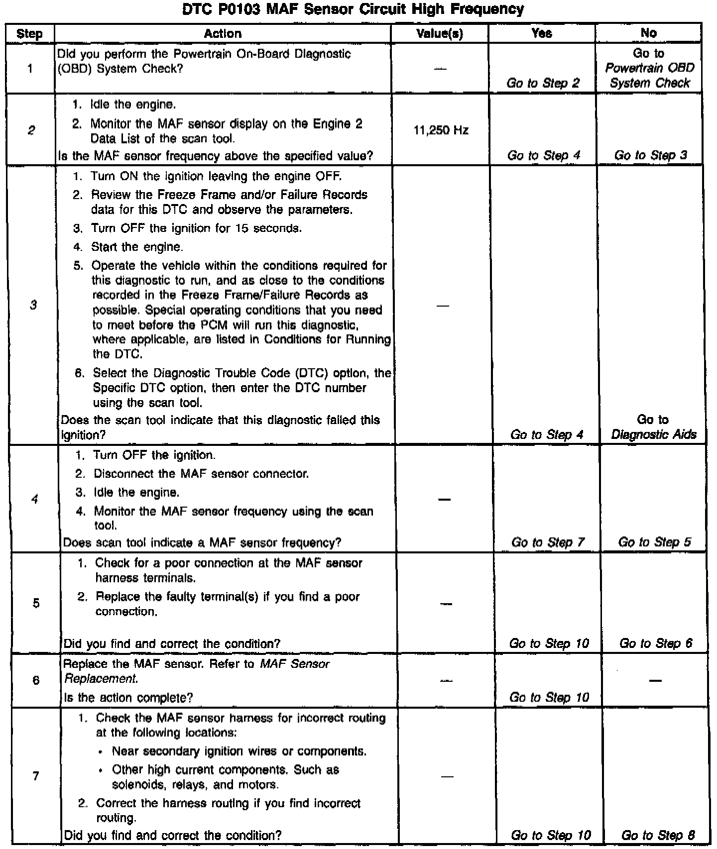
Diagnostic Chart:
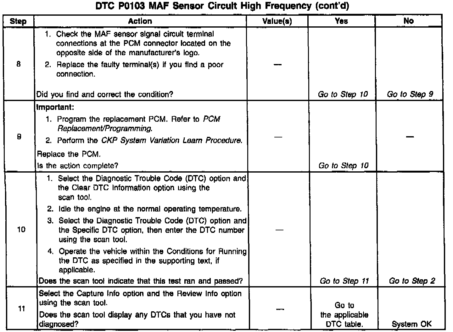
Wiring Diagram:
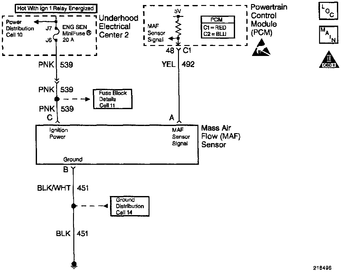
CIRCUIT DESCRIPTION
The Mass Air Flow (MAF) sensor measures the amount of air ingested by the engine. The direct measurement of the air entering the engine is more accurate than calculating the airflow from the MAR the IAT, and the engine speed (speed/density). The MAF sensor has a battery feed, a ground, and a signal circuit.
The MAF sensor used on this engine is a hot wire type. This engine uses the MAF sensor in order to measure air flow rate. The MAF output frequency is a function of the power required to keep the air flow sensing elements (hot wires) at a fixed temperature above the ambient temperature. Air flowing through the sensor cools the sensing elements. The amount of cooling is proportional to the amount of air flow. The MAF sensor requires a greater amount of current in order to maintain the hot wires at a constant temperature as the air flow increases. The MAF sensor converts the changes in current draw to a frequency signal read by the PCM. The PCM calculates the air flow (grams per second) based on this signal.
The PCM monitors the MAF sensor frequency. The PCM determines if the sensor is stuck low, stuck high, not providing the airflow value expected for a given operating condition, or that the signal appears to be stuck based on a lack of signal variation expected during the normal operation. This diagnostic checks for too low an airflow rate. This DTC sets when the PCM detects that the MAF sensor frequency is below a predetermined value.
CONDITIONS FOR RUNNING THE DTC
- The engine speed is greater than 300 RPM.
- The system voltage is greater than 8.0 volts.
CONDITIONS FOR SETTING THE DTC
- The MAF frequency is greater than 11,250 Hz.
- All conditions met for less than 1 second.
ACTION TAKEN WHEN THE DTC SETS
- The PCM illuminates the Malfunction Indicator Lamp (MIL) when the diagnostic runs and fails.
- The PCM utilizes speed density (RPM, MAP, IAT) for fuel management.
- The PCM records the operating conditions at the time the diagnostic fails. The PCM stores this information in the Freeze Frame and/or the Failure Records.
CONDITIONS FOR CLEARING THE MIL/DTC
- The PCM turns the MIL OFF after three consecutive drive trips that the diagnostic runs and does not fail.
- A last test failed (current DTC) clears when the diagnostic runs and does not fail.
- A History DTC clears after forty consecutive warm-up cycles, if this or any other emission related diagnostic does not report any failures.
- The PCM battery voltage is interrupted.
- Use a scan tool in order to clear the MIL/DTC.
DIAGNOSTIC AIDS
- Water entering the air intake system that reaches the MAF sensor could cause this DTC to set. The water rapidly cools the hot wires in the sensor, causing a false indication of excessive airflow. Check the following areas for evidence (witness marks) of water intrusion:
- AIR system.
- Intake air system.
- Inspect the IGN relay for proper operation if you cannot find any problems with the ignition feed circuit to the component. Probe both sides of the fuse with a test lamp connected to ground in order to determine if a voltage is supplied to the fuse. Refer to Ignition Relay Diagnosis. Ignition Relay Diagnosis
- The following may cause an intermittent:
- Mis-routed harness.
- Rubbed through wire insulation.
- Broken wire inside the insulation.
- A poor connection in the ignition feed circuit to the MAF sensor can cause a DTC P0103 to set.
For an intermittent, refer to Symptoms. Testing and Inspection
TEST DESCRIPTION
The numbers below refer to the step numbers on the diagnostic table.
2. Monitoring the MAF sensor frequency determines if the fault is present or the malfunction is intermittent. A poor connection at the MAF sensor or at the fuse causes this DTC to set. For any test that requires probing the PCM or component harness connectors, use the Connector Test Adapter kit J 35616-A Using this kit will prevent any damage to the harness connector terminals.
3. Using the Freeze Frame and/or Failure Records data may aid in locating an intermittent condition. If you cannot duplicate the DTC, the information included in the Freeze Frame and/or Failure Records data can help determine how many miles since the DTC set. The Fail Counter and Pass Counter can also help determine how many ignition cycles the diagnostic reported a pass and/or a fail. Operate the vehicle within the same freeze frame conditions (RPM, load, vehicle speed, temperature etc.) that you observed. This will isolate when the DTC failed. For any test that requires probing the PCM or component harness connectors, use the Connector Test Adapter kit J 35616-A. Using this kit prevents any damage to the harness connector terminals.
4. This step checks for electro-magnetic interference on the MAF sensor signal circuit. There should be no signal indicated on the scan tool with the sensor disconnected.