C0110
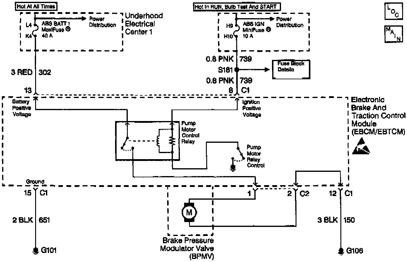
Part 1 Of 2:
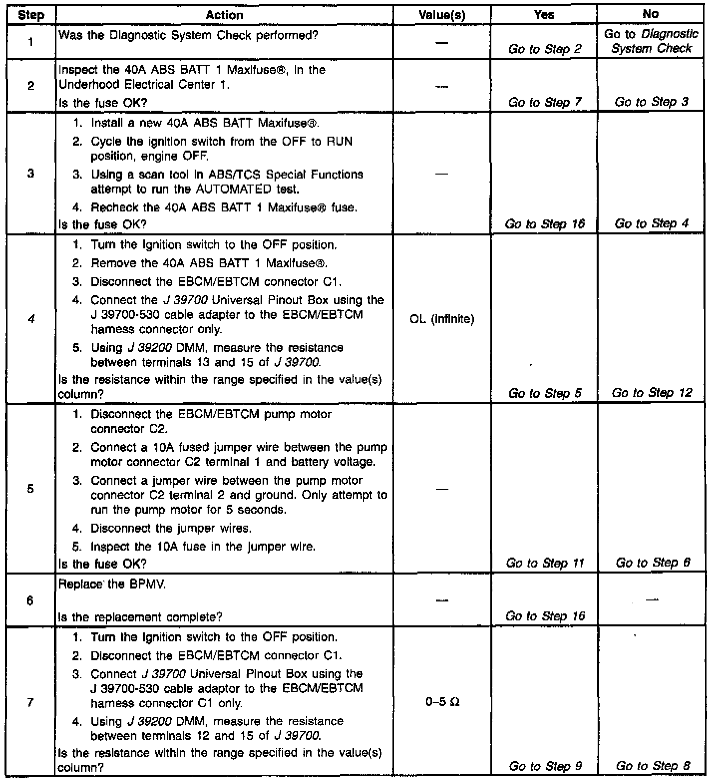
Part 2 Of 2:
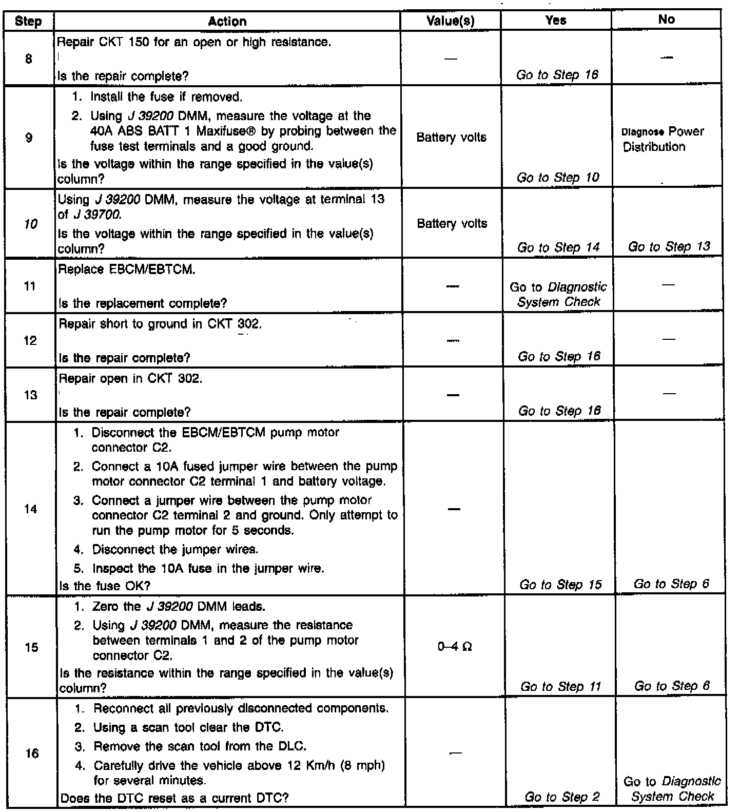
CIRCUIT DESCRIPTION
The pump motor is an integral part of the Brake Pressure Modulator Valve (BPMV), while the pump motor relay is integral to the EBCM/EBTCM. The pump motor relay is not engaged during normal system operation. When ABS or Traction Control System (TCS) operation is required the EBCM/EBTCM activates the pump motor relay and battery power is provided to the pump motor.
CONDITIONS FOR SETTING THE DTC
^ Pump motor voltage is not present 60 milliseconds after activation of the pump motor relay.
^ Pump motor voltage is present for more than 2.5 seconds with no activation of the pump motor relay.
^ Pump motor voltage is not present for 40 milliseconds after the pump motor relay is commanded off.
ACTION TAKEN WHEN THE DTC SETS
^ A malfunction Diagnostic Trouble Code (DTC) stores.
^ The ABS/TCS disables.
^ The amber ABS/TCS indicator(s) turn on.
^ The Red BRAKE Warning indicator turns on.
CONDITIONS FOR CLEARING THE DTC
^ The condition responsible for setting the DTC no longer exists and the scan tool Clear DTCs function is used.
^ 100 ignition cycles pass with no DTC(s) detected.
Important: After the DTC is cleared using ignition cycle default, the vehicle must be driven above 12 km/h (8 mph) for the ABS/TCS indicator(s) to turn off.
DIAGNOSTIC AIDS
^ It is very important that a thorough inspection of the wiring and connectors be performed. Failure to carefully and fully inspect wiring and connectors may result in misdiagnosis, causing part replacement with reappearance of the malfunction.
^ Thoroughly inspect any circuitry that may be causing the complaint for the following conditions:
- Backed out terminals
- Improper mating
- Broken locks
- Improperly formed or damaged terminals
- Poor terminal-to-wiring connections
- Physical damage to the wiring harness
^ The following conditions may cause an intermittent malfunction:
- A poor connection
- Rubbed-through wire insulation
- A broken wire inside the insulation
^ If an intermittent malfunction exists refer to "Troubleshooting Procedures" in Diagrams for further diagnosis.
TEST DESCRIPTION
The numbers below refer to step numbers on the diagnostic table.
4. This step checks for a short to ground in CKT 302.
10. This step checks for an open in CKT 302.