Propeller Shaft Replacement
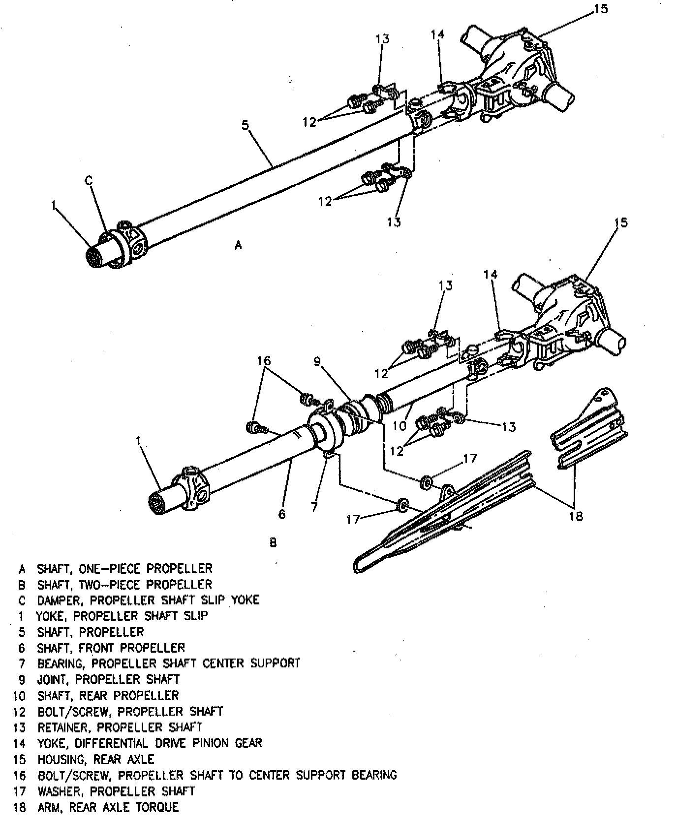
REMOVE OR DISCONNECT
Important: The two-piece propeller shaft, and center support bearing used with the 3800 (VIN K) engine are not serviceable separately. The propeller shaft and support bearing should be replaced as a complete assembly only.
NOTICE: Do not strike or drop the propeller shaft, or allow the universal joints to bend to extreme angles, as internal joint damage might occur.
1. Raise and suitably support vehicle.
2. Mark relationship of propeller shaft (5 or 10) to pinion gear yoke (14).
3. Bolts/screws (16) from center support bearing (7), if removing two-piece propeller shaft.
4. Center support bearing (7) and washers (17) from torque arm (18), if removing two-piece propeller shaft.
5. Propeller shaft bolts/screws (12).
6. Propeller shaft retainers (13).
7. Propeller shaft (5 or 6 and 10) by withdrawing slip yoke (1) from transmission, moving propeller shaft (5 or 6 and 10) rearward and passing it under housing (15).
- Support propeller shaft (5 or 6 and 10) during removal.
- If bearing caps are loose, tape them together to prevent dropping and losing needle roller bearings.
Inspect
1. Transmission output shaft splices for burrs.
2. Outer diameter of slip yoke (1) for burrs.
3. Splines of slip yoke (1) for damage, twisting or wear. They should agree in number and fit with transmission output shaft splines.
4. Pinion gear yoke (14) at universal joint cap connecting surface for burrs or foreign material.
INSTALL OR CONNECT
NOTICE: Always use the correct fastener in the correct location. When you replace a fastener, use ONLY the exact part number for that application. The Manufacturer will call out those fasteners that require a replacement after removal. The Manufacturer will also call out the fasteners that require thread lockers or thread sealant. UNLESS OTHER WISE SPECIFIED, do not use supplemental coatings (paints, greases, or other corrosion inhibitors) on the threaded fasteners or fastener joint interfaces. Generally, such coatings adversely affect the fastener torque and the joint clamping force, and may damage the fastener. When you install fasteners, use the correct tightening sequence and specifications. Following these instructions can help you avoid damage to parts and systems.
NOTICE: The propeller shaft must be supported carefully during handling to avoid jamming or bending of parts.
Important: To prevent transmission seal damage, do not place any tool between the propeller shaft slip yoke and splines.
1. Slip yoke (1) onto transmission output shaft after lubricating with chassis lubricant.
2. Rear of propeller shaft (5 or 10) to pinion gear yoke (14).
Important: When making the rear propeller shaft connection, be sure to align the mark on pinion gear yoke (14) with the mark on propeller shaft (5 or 10).
3. Rear universal joint to pinion gear yoke (14), making sure bearing caps are properly seated.
4. Propeller shaft retainers (13).
5. Propeller shaft bolts/screws (12).
Tighten
- Propeller shaft bolts/screws (12) evenly to 22 Nm (16 ft. lbs.).
6. Washers (17) and center supped bearing (7) to torque arm (18), if removed.
7. Bolts/screws (16) to center support bearing (7), if removed.
- Tighten Propeller shaft-to-center support bearing bolts/screws (16) to 50 Nm (37 ft. lbs.).
8. Lower vehicle.