Strobe Light Method
If a strobe-light type wheel balancer is used, it will help in the balancing of the propeller shaft.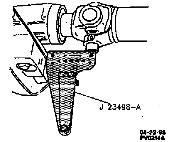
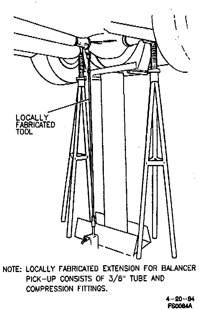
The balance pick-up unit should be placed directly under the nose of the rear axle housing and as far forward as possible. Make up an extension for the balance pick-up unit by using 3/8-inch tube and compression fittings.
1. Raise the vehicle on twin post hoist so that vehicle is supported on rear axle housing and rear wheels are free to rotate. Lower rear hoist and allow rear axle to rest on jackstands.
2. Remove both rear tires and wheels.
3. Install wheel nuts with flat sides next to rear brake drums or rotors. System is now released and free to respond to propeller shaft (5).
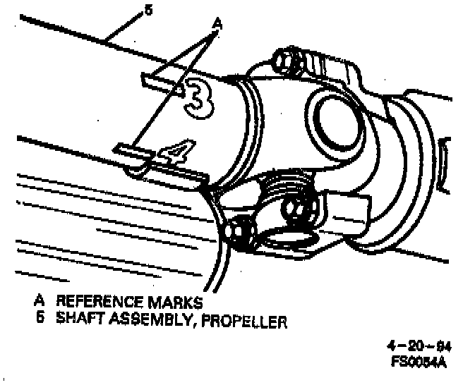
4. Mark and number propeller shaft (5) at four points, 90° apart, at rear of propeller shaft (5) just forward of balance weights.
5. Place strobe light wheel balancer pick-up under pinion gear yoke in contact with rear axle housing and as far forward as possible.
CAUTION: Do not run the vehicle faster than 88 km/h (55 mph). Stay clear of the universal joint and balance weight areas to avoid possible personal injury. Do not run the vehicle on the hoist for extended periods due to the danger of overheating the transmission or the engine.
6. Run vehicle in gear at speed where disturbance is at its peak.
7. Allow driveline to stabilize by holding at steady speed.
8. Point strobe light up at spinning propeller shaft (5) and note position of one of the reference numbers.
NOTICE: Allow the driveline components to stop rotating with the transmission in "NEUTRAL" before shifting the transmission in "PARK" or parts may be damaged.
9. Shut off engine.
10. Position propeller shaft (5) so reference numbers will be in same position as was noted while propeller shaft (5) was rotating.
^ When strobe light flashed, heaviest point of propeller shaft (5) was at bottom (6 o'clock). To balance propeller shaft (5), it would be necessary to apply balancing weights (hose clamps) 180° away from heaviest point or at top of propeller shaft (5) (12 o'clock).
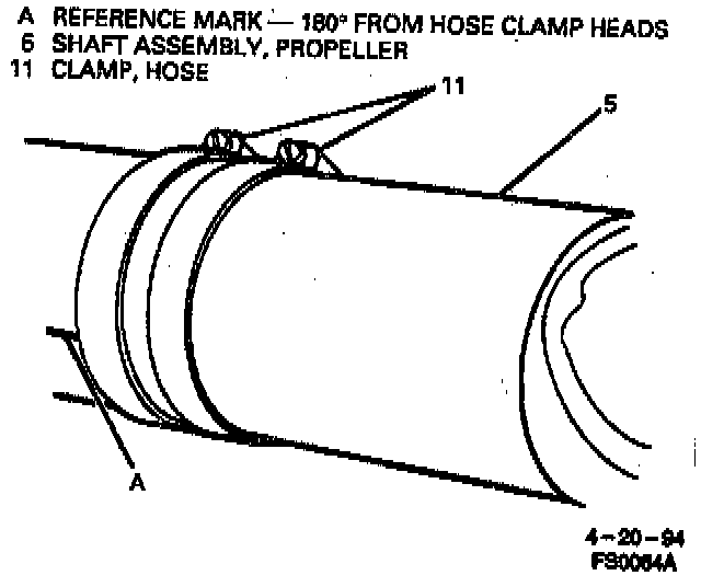
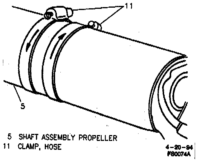
11. Install two screw-type clamps (11) on propeller shaft (5) as close to rear as possible. Position both clamp heads 180° from heaviest point of propeller shaft (5) as indicated by strobe light. Tighten clamps (11).
12. Run vehicle through speed range 81-88 km/h (50-55 mph).
a. If disturbance is not gone and strobe light shows clamp heads at bottom (6 o'clock) of propeller shaft (5), go to step 13.
b. If strobe light shows two clamp heads at top of propeller shaft (5), add one more clamp (11) and check.
c. If strobe light shows three clamp heads at top of propeller shaft (5), remove propeller shaft (5) and rotate 180° on pinion gear yoke. Check again, without clamps (11).
d. Repeat balancing, starting with step 11.
Important: Do not use more than three clamps (11) to balance propeller shaft (5).
e. If propeller shaft (5) still needs more than three clamps (11) at same clock position, replace propeller shaft (5).
f. If clamps (11) are also 180° from their original position after rotating propeller shaft (5) 180°, pinion gear yoke is out of balance and must be replaced.
g. If strobe light shows clamps (11) at bottom of propeller shaft (5), but disturbance still exists, go to step 13.
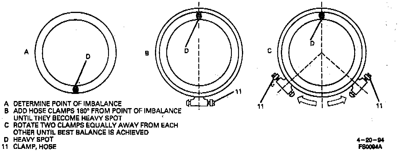
13. Rotate two of the clamps (11) equally away from each other toward top (one on each side of the position) in small increments until best balance is achieved. In some cases it may be necessary to use one clamp (11) or possibly three clamps (11) in order to obtain good balance. Replace propeller shaft (5) if three clamps (11) do not correct problem.
14. Remove wheel nuts.
15. Install tires and wheels.
16. Remove strobe light and lower vehicle.
17. Road test vehicle to check final balance.
- A small vibration felt while vehicle is on hoist, may not be noticed on road test.