Axle Shaft Assembly: Service and Repair
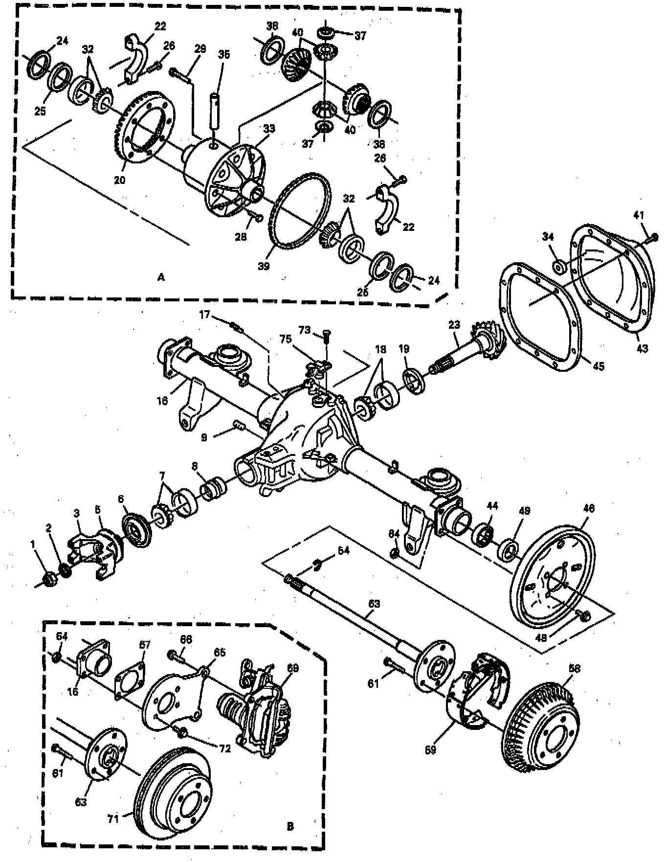
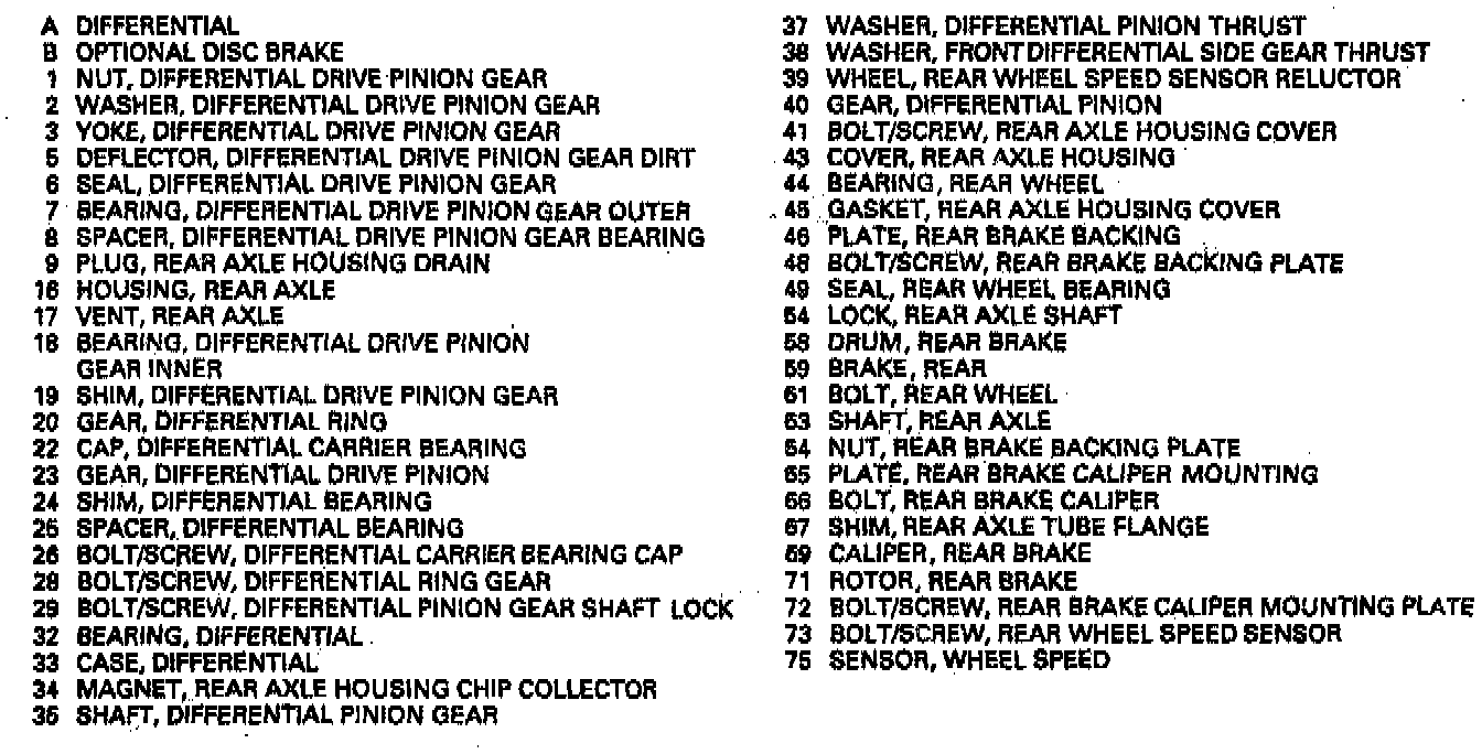
REAR AXLE SHAFTStandard Rear Axle Assembly:
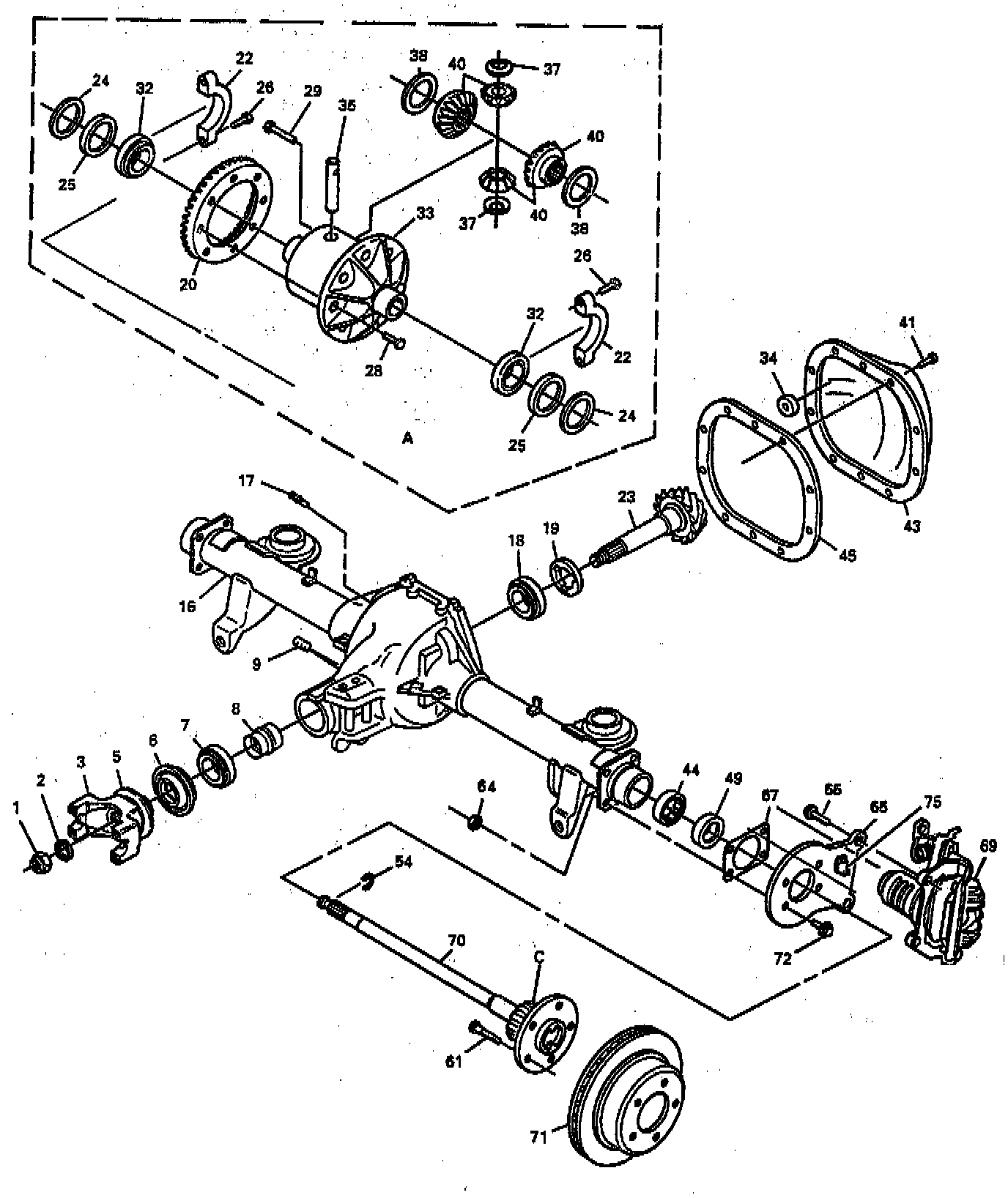
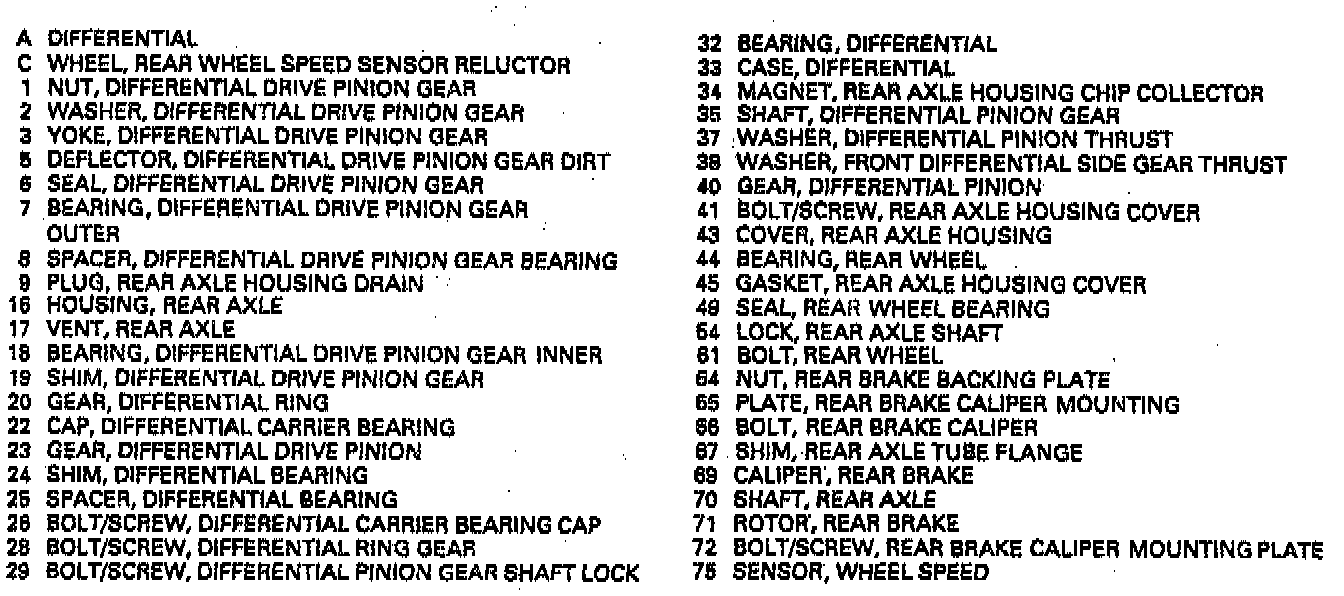
Rear Axle Assembly With Traction Control (Acceleration Slip Regulation):
^ Tool Required:
- J 39446 ABS Exciter Ring Protector Kit
REMOVE OR DISCONNECT
1. Rear tire and wheel.
2. Rear brake drum and components, if equipped.
3. Rear brake rotor, if equipped.
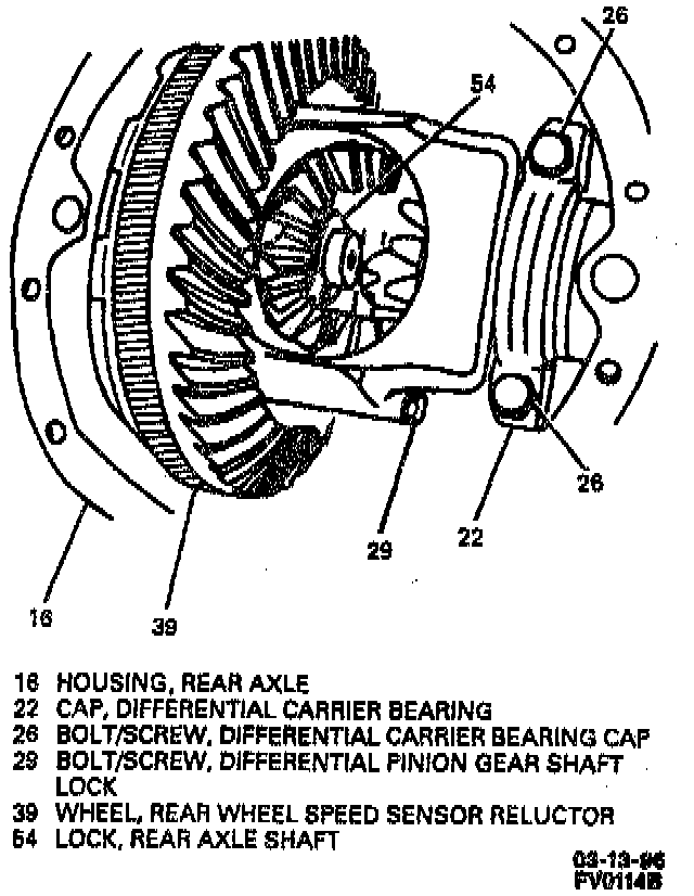
4. Rear axle housing cover.
5. Install J 39446 to speed sensor reluctor wheel (39) on vehicles equipped with non-traction control rear axles.
6. Pinion gear shaft lock bolt/screw (29) from differential case (33).
7. Pinion gear shaft (35) from differential case (33).
8. Rear axle shaft lock (54).
^ Access by pushing flanged end of axle shaft (63 or 70) into rear axle housing (16).
9. Rear axle shaft (63 or 70) from rear axle housing (16), being careful not to damage rear wheel bearing seal (49).
Important: If vehicle is equipped with traction control be careful not to damage rear wheel speed sensor reluctor wheel located on axle shaft when removing the axle shaft. If damage has occurred to the rear wheel speed sensor reluctor wheel, the rear axle shaft must be replaced.
INSTALL OR CONNECT
NOTICE: Always use the correct fastener in the correct location. When you replace a fastener, use ONLY the exact part number for that application. The Manufacturer will call out those fasteners that require a replacement after removal. The Manufacturer will also call out the fasteners that require thread lockers or thread sealant. UNLESS OTHER WISE SPECIFIED, do not use supplemental coatings (paints, greases, or other corrosion inhibitors) on the threaded fasteners or fastener joint interfaces. Generally, such coatings adversely affect the fastener torque and the joint clamping force, and may damage the fastener. When you install fasteners, use the correct tightening sequence and specifications. Following these instructions can help you avoid damage to parts and systems.
1. Rear axle shaft (63 or 70) into place, taking care that splines on end of axle shaft (63 or 70) do not damage rear wheel bearing seal (49) and that they engage with splines of differential side gear (40).
2. Rear axle shaft lock (54).
- Push axle shaft (63 or 70) outward so that rear axle shaft lock (54) seats in counterbore of differential side gear (40).
3. Pinion gear shaft (35) through differential case (33), pinion gear thrust washers (37) and pinion gears (36), aligning hole in pinion gear shaft (35) with rear axle shaft lock bolt/screw hole in differential case (33).
4. Pinion gear shaft lock bolt/screw (29).
Important: Coat pinion gear shaft lock bolt/screw (29) with Loctite 242 or equivalent before installing.
Tighten
Differential pinion gear shaft lock bolt/screw (29) to 36 Nm (27 lb ft).
5. Remove J 39446 from speed sensor reluctor wheel (39), if vehicle is equipped with standard rear axle. If new speed sensor reluctor wheel (39) was installed, remove protective covering and throw away.
6. Rear axle housing cover.
7. Rear brake rotor, if equipped.
8. Rear brake drum and components, if equipped.
9. Rear tire and wheel.