Front Suspension
^ Tools Required:
- J 34013-B Strut Spring Compressor
- J 34013-114 Modular Shock Compressor Adapter
- J 34013-88 Strut Compressor Adapter
- J 39642 Modular Shock Nut Removal Set, 15 mm (0.60 inch)
- J 34013-115 Modular Shock Alignment Rod
- Or Equivalents
REMOVE OR DISCONNECT
1. Brake master cylinder nuts (driver-side only).
2. Move brake master cylinder aside (driver-side only).
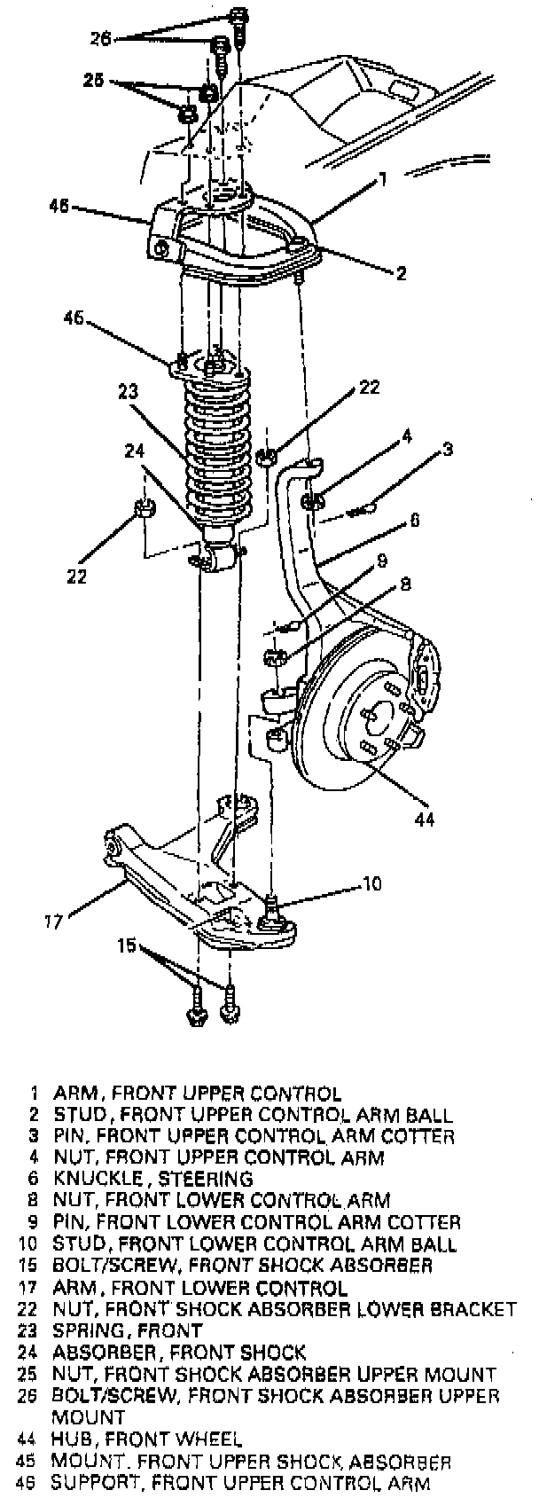
3. Bolts/screws (26) and nuts (25).
4. Raise and suitably support vehicle.
5. Special security wheel lock nut, if equipped.
6. Tire and wheel.
7. Stabilizer shaft link. Refer to "Stabilizer Shaft Link".
8. Nuts (22).
9. Bolts/screws (15).
10. Separate lower ball stud from steering knuckle. Refer to "Control Arm Ball Stud Replacement".
Important: Be sure to mark with chalk or paint (do not scribe) the lower mount location relative to the upper mount location before removing the shock absorber.
11. Shock absorber and spring (24 and 23).
Disassemble
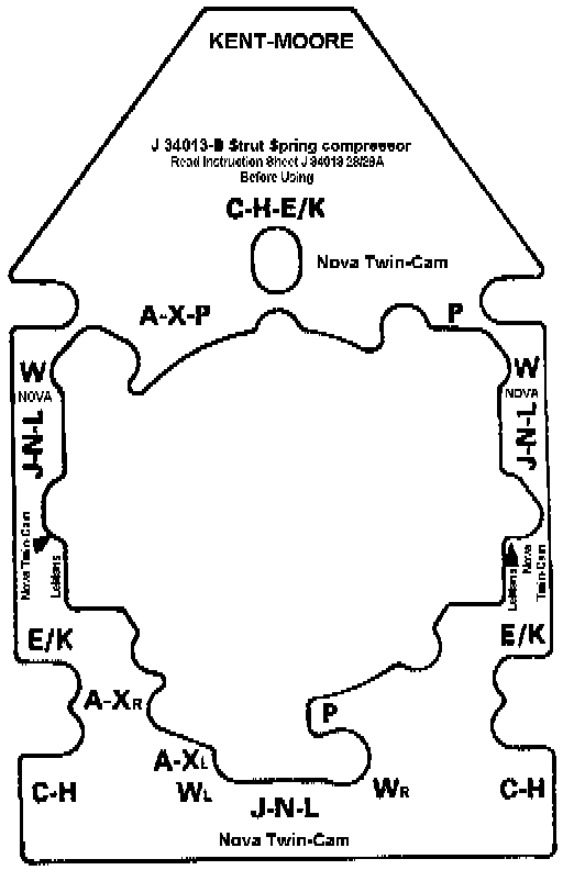
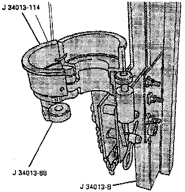
1. Install J 34013-114 to J 34013-B. Use wing nuts to secure tool to mounting holes C-H (lower left corner) and P (upper right corner) for driver-side shock absorber and to secure tool to mounting holes A-X-P (upper left corner) and C-H (lower right corner) for passenger-side shock absorber.
Important: Be sure J 34013-114 and J 34013-88 are aligned so they can open and close together. If the tools are not aligned properly, they will not open.
2. Install J 34013-114 and J 34013-88.
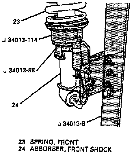
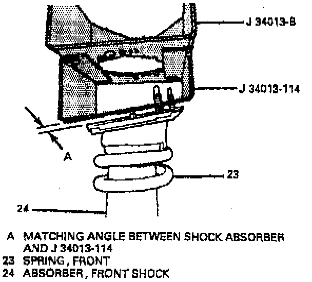
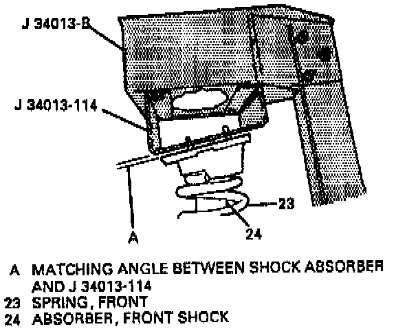
Important: Be sure the top of the shock absorber is flat against J 34013-114. The shock absorber will not be aligned correctly if it does not lay flat against the tool.
3. Shock absorber to top of J 34013-114.
4. Install shock absorber into J 34013-114 and J 34013-88.
5. Close J 34013-114 and J 34013-88 and install locking pin.
Important: Be sure the mounting ears of the shock absorber are facing downward, toward the rear of J 34013-B or the shock absorber will not align properly.
6. Turn screw on J 34013-B counterclockwise to raise shock absorber up to J 34013-114. Be sure studs go through guide holes in J 34013-114 and the top of the shock absorber is flat against the tool.
CAUTION: Do not over compress spring. Severe overloading may cause tool failure which could result in bodily injury.
7. Compress front spring approximately 13 mm (0.50 inch) or three or four complete turns of the screw on J 34013-114.
8. Insert J 39642-1 on shock absorber nut, then insert J 39642-2 through J 39642-1 to hold shock absorber rod in place.
9. Remove shock absorber nut with J 39642-1 while holding shock absorber rod from rotating with J 39642-2.
10. Discard shock absorber nut.
11. Turn J 34013-B clockwise to fully relieve spring pressure.
Assemble
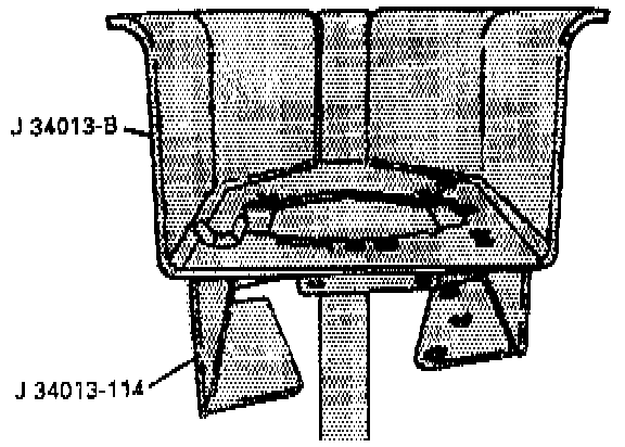
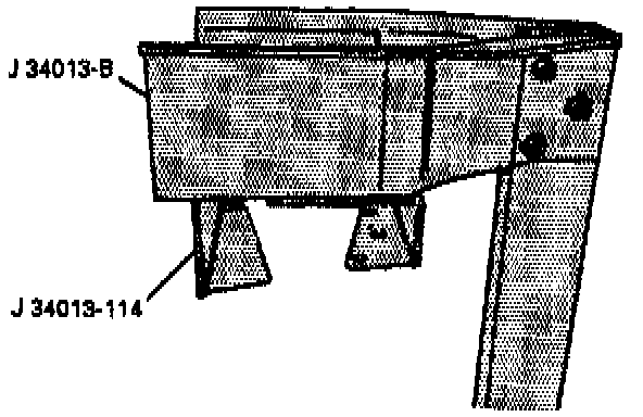
1. Install J 34013-114 to J 34013-B. Use wing nuts to secure J 34013-114 to J 34013-B mounting holes C-H (lower left corner) and P (upper right corner) for driver-side shock absorber and to secure J 34013-114 to J 34013-8 mounting holes A-X-P (upper left corner) and C-H (lower right corner) for passenger-side shock absorber.
2. Install J 34013-114 and J 34013-88.
3. Install shock absorber to J 34013-114 and J 34013-88.
Important:
^ Be sure the mounting ears of the shock absorber are facing downward, toward the rear of J 34013-B or the shock absorber will not align properly.
^ Be sure to mark with chalk or paint (do not scribe) the lower mount location relative to the upper mount location before removing the shock absorber or the shock absorber cannot be reinstalled.
4. Close J 34013-114 and J 34013-88 and engage locking pin.
5. Make sure upper and lower spring seats are positioned correctly.
6. Shock absorber to top of J 34013-114.
Important: Be sure the top of the shock absorber is flat against J 34013-114. The shock absorber will not be aligned properly if it does not lay flat against the tool.
7. Turn screw on J 34013-B counterclockwise to raise shock absorber up to J 34013-114 without compressing spring. Be sure studs on shock absorber go through guide holes in J 34013-114.
Important: Only turn the screw until the shock absorber is held in J 34013-B by itself. Do not load the spring.
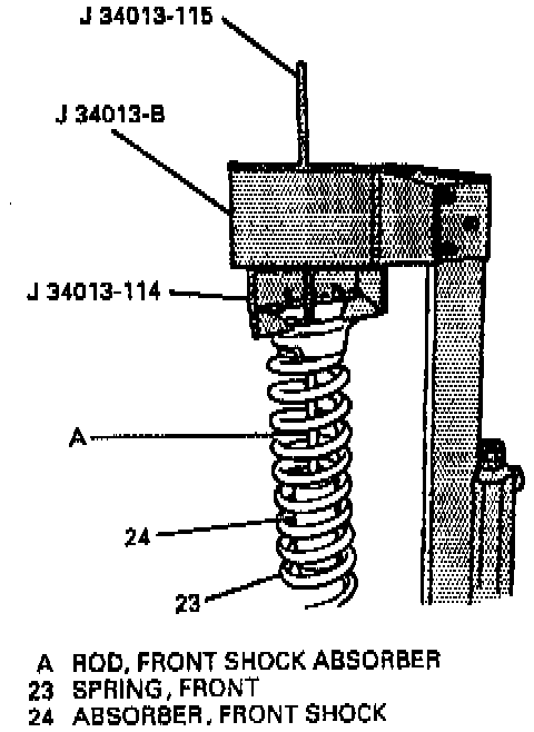
8. Place J 34013-115 down through top of J 34013-B through top of-shock absorber and onto shock absorber rod.
Important: Make sure J 34013-115 is straight with the shock absorber. If J 34013-115 is angled, repeat steps 1 through 5 until tool is straight.
CAUTION: Do not over compress spring. Severe overloading may result in tool failure which could result in bodily injury.
9. Turn operating screw clockwise to compress spring until threaded portion of the shock absorber rod is through the top of the shock absorber.
10. Remove J 34013-115.
Important: When installing front shock absorber nut, always replace it with a new one. Never install the same nut that has been removed.
11. Insert new shock absorber nut on shock absorber rod.
NOTICE: Turning the shock absorber while tightening the nut could damage the shock absorber. To prevent damage, keep the shock absorber in a stationary position when tightening the nut.
12. Place J 39642-1 on shock absorber nut.
13. Insert J 39642-2 through J 39642-1 and tighten shock absorber nut.
14. Tighten shock absorber nut while holding onto J 39642-2.
15. Remove shock absorber from J 34013-B.
INSTALL OR CONNECT
NOTICE: Always use the correct fastener in the correct location. When you replace a fastener, use ONLY the exact part number for that application. The manufacturer will call out those fasteners that require a replacement after removal. The manufacturer will also call out the fasteners that require thread lockers or thread sealant. UNLESS OTHERWISE SPECIFIED, do not use supplemental coatings (paints, greases, or other corrosion inhibitors) on threaded fasteners or fastener joint interfaces. Generally, such coatings adversely affect the fastener torque and the joint clamping force, and may damage the fastener. When you install fasteners, use the correct tightening sequence and specifications. Following these instructions can help you avoid damage to parts and systems.
1. Position shock absorber and spring (24 and 23) to lower control arm (17).
2. Bolts/screws (15) and nuts (22).
Tighten bolts/screws (15) and nuts (22) to 65 Nm (48 ft. lbs.).
3. Lower ball stud to steering knuckle. Refer to "Control Arm Ball Stud Replacement".
4. Stabilizer shaft link. Refer to "Stabilizer Shaft Link".
5. Tire and wheel.
6. Special security wheel lock nut, if equipped.
7. Lower vehicle.
8. Hand tighten bolts/screws (26) and nuts (25).
^ Tighten:
- Bolts/screws (26) to 50 Nm (37 ft. lbs.).
- Nuts (25) to 43 Nm (32 ft. lbs.).
9. Position brake master cylinder (driver-side only).
10. Brake master cylinder nuts (driver-side only).