Upper
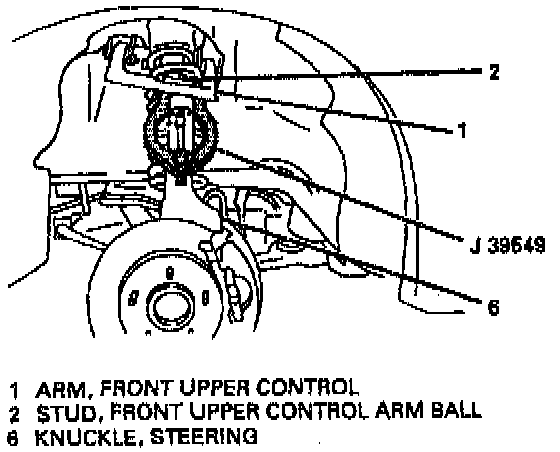
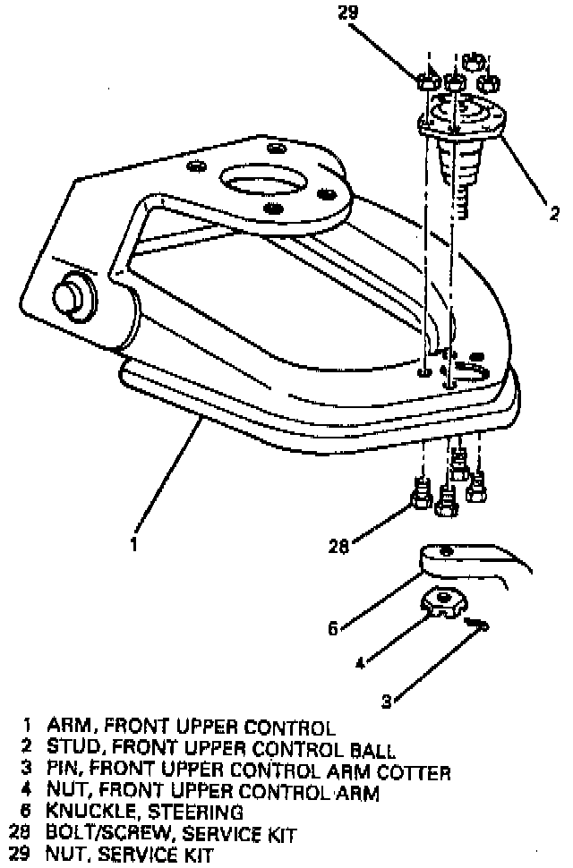
^ Tool Required:
- J 39549 Ball Joint/Tie Rod Separator
- Or Equivalent
REMOVE OR DISCONNECT
1. Raise and suitably support vehicle.
2. Special security wheel lock nut, if equipped.
3. Tire and wheel.
4. Place floor jack under shock absorber mounting location on lower control arm (17).
Important: Floor jack must remain under the shock absorber mounting location on lower control arm (17) during removal and installation to hold the spring and lower control arm in position.
5. Loosen ball stud (2) from steering knuckle (6).
6. Cotter pin (3) and nut (4).
7. Support steering knuckle (6) with floor stands.
8. Separate ball stud (2) from upper control arm (1), using J 39549.
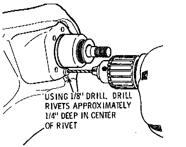
9. With upper control arm (1) in raised position, drill out four rivets approximately 6 mm (0.25 inch) deep, using 1/8-inch drill bit.
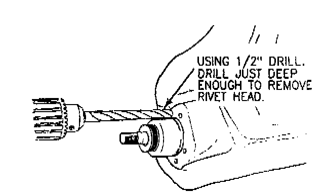
10. Drill off rivet heads, using 1/2-inch drill bit.
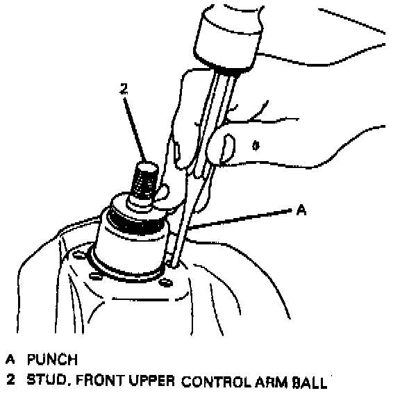
11. Punch out rivets, using small punch, and remove ball stud (2).
INSTALL OR CONNECT
NOTICE: Always use the correct fastener in the correct location. When you replace a fastener, use ONLY the exact part number for that application. The manufacturer will call out those fasteners that require a replacement after removal. The manufacturer will also call out the fasteners that require thread lockers or thread sealant. UNLESS OTHERWISE SPECIFIED, do not use supplemental coatings (paints, greases, or other corrosion inhibitors) on threaded fasteners or fastener joint interfaces. Generally, such coatings adversely affect the fastener torque and the joint clamping force, and may damage the fastener. When you install fasteners, use the correct tightening sequence and specifications. Following these instructions can help you avoid damage to parts and systems.
1. Position new ball stud (2) and install four service kit bolts/screws (28) and nuts (29). Use specifications in ball stud kit.
2. Remove temporary support from steering knuckle (6), then connect ball stud (2) to steering knuckle (6).
3. Hand start nut (4).
Important: Tighten nut enough to align slot with stud hole. Never loosen nut in order to align slot with hole.
Tighten nut (4) to 53 Nm (39 ft. lbs.).
4. Cotter pin (3).
5. Remove floor jack from under spring seat.
6. Tire and wheel.
7. Special security wheel lock nut, if equipped.
8. Lower vehicle.