Ignition Lock Cylinder
REMOVE OR DISCONNECT
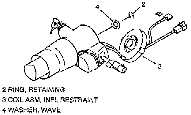
NOTICE: Place ignition to "LOCK" position to prevent uncentering coil assembly (3).
1. Disable the SIR system; Refer to "Disabling the SIR System".
2. Negative (-) battery cable.
3. Coil assembly retaining ring (2).
4. Inflatable restraint coil assembly (3).
^ Let switch hang freely if removal is not needed.
^ To remove coil (3), do steps 5 through 17.
5. Wave washer (4).
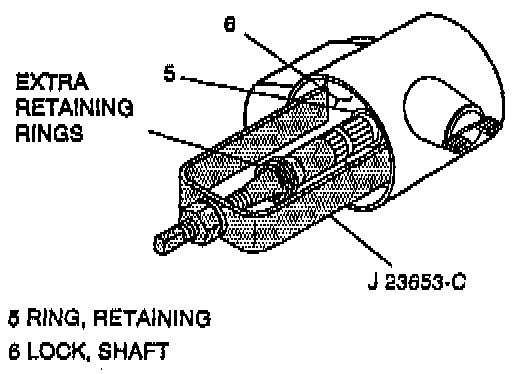
6. Shaft lock retaining ring (5) using J 23653-C to push down shaft lock (6).
^ Dispose of ring (5).
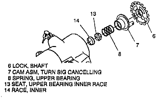
7. Shaft lock (6).
8. Turn signal canceling cam assembly (7).
9. Upper bearing spring (8).
10. Upper bearing inner race seat (13).
11. Inner race (14).
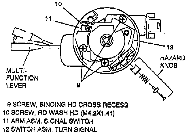
12. Turn signal to "RIGHT TURN" position (up).
13. Multi-function lever and hazard knob assembly.
14. Screw (10) and signal switch arm (11).
15. Turn signal switch screws (9).
16. Turn signal switch assembly (12).
^ Let switch hang freely if removal is not needed.
^ To remove switch (12):
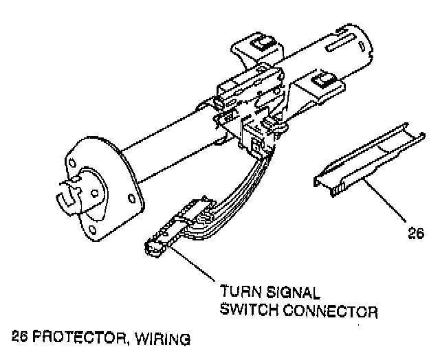
A. Turn signal switch connector from bulkhead connector.
B. Wiring protector (26).
C. Gently pull wire harness through column.
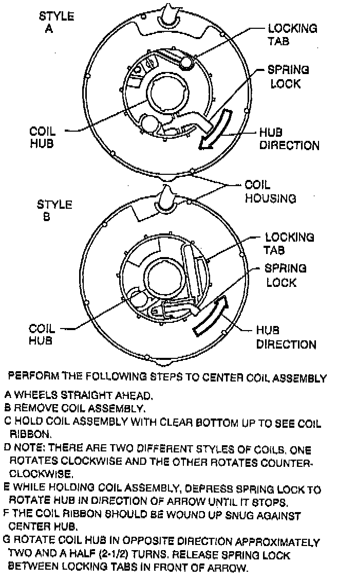
NOTICE: Coil assembly (3) will become uncentered if:
1) Steering column is separated from steering gear and is allowed to rotate, or
2) Centering spring is pushed down, letting hub rotate while coil(3) is removed from steering column.
17. Inflatable restraint coil assembly (3) with wire harness from column assembly.
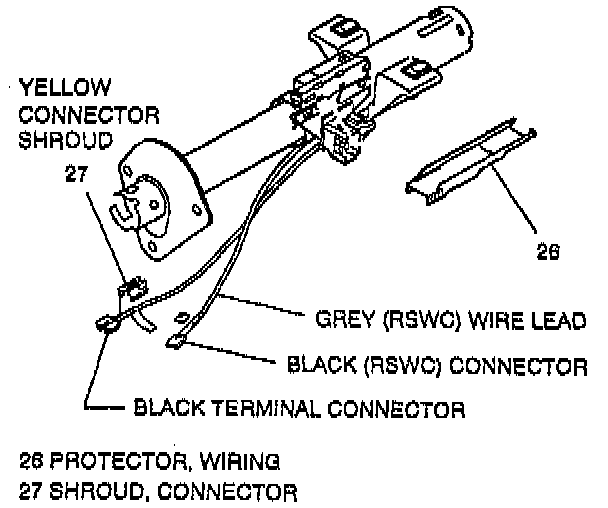
A. Wiring protector (26).
B. Attach two lengths of mechanics wire to coil terminal connectors to aid in reassembly.
C. Gently pull wires through column.
18. Key from pass key lock cylinder set (20).
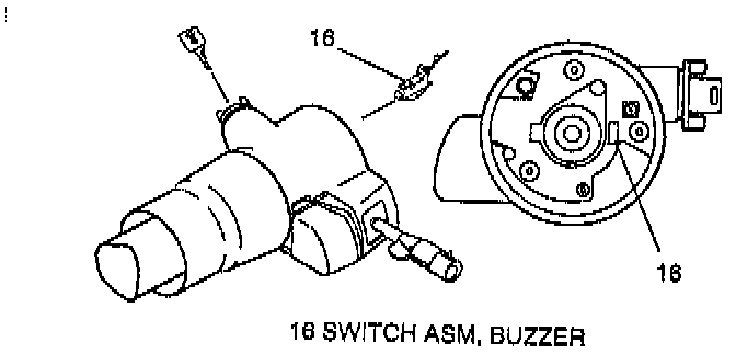
19. Buzzer switch assembly (16).
20. Reinsert key in pass key lock cylinder (20)
^ Key in "LOCK" position.
21. Lock retaining screw (18).
22. Pass key lock cylinder (20) and harness.
^ To remove lock cylinder (20):
A. Terminal connector from bulkhead connector.
B. Wiring protector (26).
C. Attach a length of mechanics wire to terminal to aid in reassembly.
D. Retaining clip from housing cover (19) and gently pull wire harness through column.
INSTALL OR CONNECT
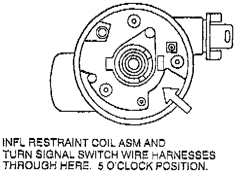
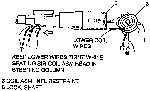
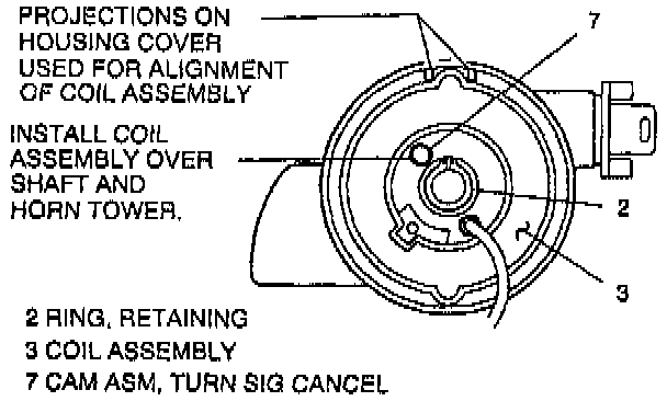
NOTICE: Always use the correct fastener in the correct location. When you replace a fastener, use ONLY the exact part number for that application. The manufacturer will call out those fasteners that require a replacement after removal. The manufacturer will also call out the fasteners that require thread lockers or thread sealant. UNLESS OTHERWISE SPECIFIED, do not use supplemental coatings (paints, greases, or other corrosion inhibitors) on threaded fasteners or fastener joint interfaces. Generally, such coatings adversely affect the fastener torque and the joint clamping force, and may damage the fastener. When you install fasteners, use the correct tightening sequence and specifications. Following these instructions can help you avoid damage to parts and systems.
NOTICE: Ensure all fasteners are securely seated before applying needed torque. Failure to do may result in component damage or malfunctioning of steering column.
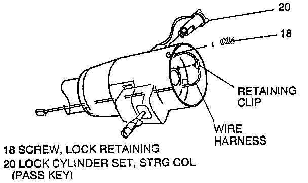
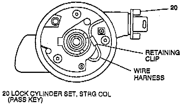
NOTICE: Route wire from pass key lock cylinder as shown and snap retaining clip into hole in housing (19). Failure to do so may result in component damage of malfunction of pass key lock cylinder.
1. Pass key lock cylinder (20).
2. Lock retaining screw (18).
A. Wire terminal through column and snap retaining clip into hole in housing.
B. Lock cylinder (20) connector to vehicle wire harness.
^ Tighten screw (18) to 2.5 Nm (22 lb in).
3. Key from pass key lock cylinder set (20).
4. Buzzer switch assembly (16).
5. Reinstall key in pass key lock cylinder set (20).
^ Key in "OFF-LOCK" position.
6. Turn signal switch assembly (12) wire harness through steering column.
A. Let switch hang freely.
B. Switch connector to bulkhead connector.
7. Coil assembly (3) wire harness through column.
^ Let coil hang freely.
8. Turn signal switch assembly (12) and screws:(9);
^ Tighten screws (9) to 3.4 Nm (30 lb in).
9. Signal switch arm (11) with screw (10).
^ Tighten screw (10) to 2.3 Nm (20 lb in).
10. Hazard knob assembly and multi-function lever.
11. Inner race (14).
12. Upper bearing-inner race seat (13).
13. Upper bearing spring (8).
14. Turn signal canceling cam assembly (7).
^ Lubricate with grease, synthetic (service kit).
15. Shaft lock (6).
16. New shaft lock retaining ring (5) using J 23653-C to push down shaft lock (6).
^ Ring (5) must be firmly seated in groove on shaft.
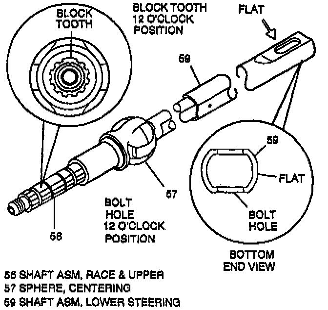
NOTICE: Set steering shaft so that block tooth on upper steering shaft (56) is at the 12 o'clock position, wheels on vehicle should be straight ahead, then set ignition switch to "LOCK" position, to ensure no damage to coil assembly (3).
17. Wave washer (4).
NOTICE: Coil assembly (3) will become uncentered if:
1) Steering column is separated from steering gear and is allowed to rotate, or
2) Centering spring is pushed down, letting hub rotate while coil is removed from column.
NOTICE: If a new coil assembly (3) is being installed, assemble pre-centered coil assembly (3) to steering column. Remove centering tab and dispose.
NOTICE: Sir coil assembly wires must be kept tight with no slack while installing SIR coil assembly. Failure to do so may cause wires to be kinked near shaft lock area and cut when steering wheel is turned.
18. Ensure coil assembly (3) hub is centered.
19. Coil assembly (3).
A. Pull wires tight while positioning SIR coil to steering shaft.
B. Align opening in coil with horn tower and "locating bump" between two tabs on housing cover.
C. Seat coil assembly into steering column.
20. Coil assembly retaining ring (2).
^ Ring (2) must be firmly seated in groove on shaft.
NOTICE: Gently pull lower coil assembly, turn signal, pass key, and pivot & (pulse) wires to remove any wire kinks that may be inside steering column assembly. Failure to do so may cause damage to wire harness.
21. Wiring protector (26).
22. Refer to "Steering Wheel And Column On-Vehicle Service" to complete remaining steering column assembly.
23. Negative (-) battery cable.
24. If all service operations are completed, enable the SIR system; refer to "Enabling the SIR System".