Data Link Connector Diagnosis
Wiring Diagram:
Circuit Description
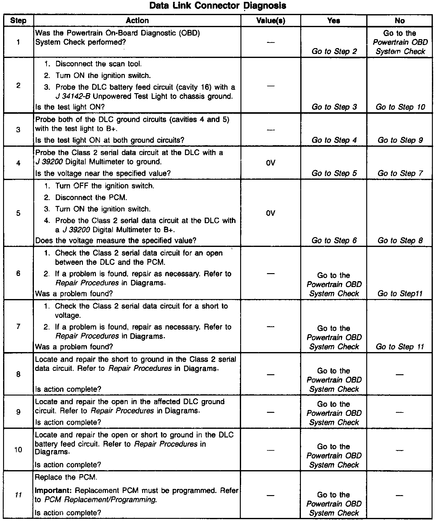
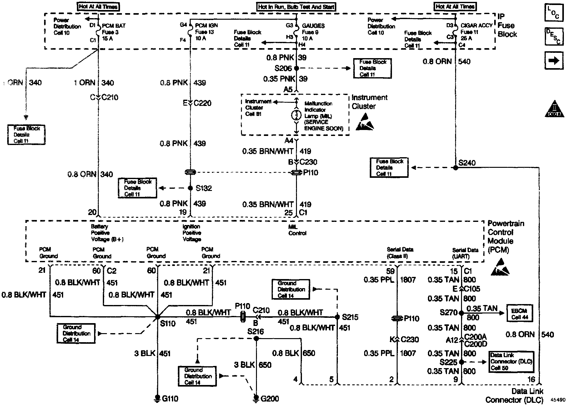
The Class 2 serial data circuit to the Data Link Connector (DLC) allows bi-directional communication between the PCM and the scan tool. If communication between the scan tool and the PCM cannot be established, the procedure in the DLC Diagnosis table should be used to diagnose the condition.
Diagnostic Aids
Check the following items:
- For the PCM to establish communication with the scan tool, system voltage must be between 9.0 and 16.0 volts. If system voltage is not within this range, refer to Charging System for diagnosis.
- Ensure that the correct application (model year, car line, VIN code) has been selected on the scan tool; if communication still cannot be established try the scan tool on another vehicle to ensure that the scan tool, Vehicle Interface Module, or cables are not the cause of the condition.
- An intermittent may be caused by a poor connection, rubbed through wire insulation or a wire broken inside the insulation. Check for poor connections or a damaged harness. Inspect the PCM harness and connectors for improper mating, broken locks, improperly formed or damaged terminals, poor terminal to wire connection, and damaged harness.
Test Description
Number(s) below refer to the Step number(s) on the Diagnostic Table:
11. This vehicle is equipped with a PCM which utilizes an Electrically Erasable Programmable Read Only Memory (EEPROM). When the PCM is being replaced, the new PCM must be programmed.