Ignition System (3.4L VIN X "W" Body)
- Disconnect tachometer wire (if equipped). A shorted tachometer or tachometer circuit will prevent vehicle from starting.
- Install scan tester. Check for stored PCM trouble codes. can TP sensor voltage. If TP sensor reading is greater than 2.5 volts, use Code P0123 chart first. Scan PASS-Key(R) II system. Scan tester should read "Enabled". If not, diagnose PASS-Key(R) system.
- Disconnect camshaft position sensor and attempt to start engine. If engine starts, use Code P0341. If engine has not been started for at least 8 hours, intake air temperature should be close to CTS scan temperature. If not, replace coolant temperature sensor.
- Reconnect camshaft position sensor. Depress accelerator to about 25 percent throttle angle. Attempt to start engine. If engine starts, diagnose Idle Air Control (IAC) system. See appropriate I - SYS/COMP TESTS article in the ENGINE PERFORMANCE section below. If engine did not start, go to next step.
- I - SYSTEM/COMPONENT TESTS - 3.1L
- I - SYSTEM/COMPONENT TESTS - 3.4L
- I - SYSTEM/COMPONENT TESTS - 3.8L
- Turn ignition off. Check fuel pressure. Fuel pressure should be 40-47 psi (2.8-3.3 kg/cm2
) and holding. If fuel pressure is as specified, go to next step. If fuel pressure is not as specified, diagnose entire fuel system.
- Crank engine and check for spark using Spark Tester (ST-125) on spark plug wires No. 1, 3 and 5. Check one wire at a time. Ground companion spark plug wire and leave other wires connected to spark plugs while cranking. If spark is not present on either wires or spark is present on one spark wire only, go to next step. If spark is present on all wires, go to step 8). If spark is not present on any wires, check for poor ignition control module connection or faulty ignition control module.
- Check spark plug wire resistance. Resistance should be less than 30,000 ohms. Check ignition coil secondary resistance. Resistance should be 5000-8000 ohms at 70°F (21°C). Check ignition coil primary resistance. Resistance should be .5-.9 ohms at 70°F (21°C). Connect test light between ignition control module terminals for problem coil. Test light should flash while cranking engine. If test light flashed, check for poor ignition coil connection or faulty ignition coil. If test light did not flash, replace faulty ignition control module.
- Disconnect 6-wire injector jumper harness connector. Turn ignition on. Connect test light to battery voltage and probe each injector driver circuit at both sides of connector. Test light should not illuminate at each circuit. If test light illuminated, go to step 10). If test light did not illuminate, go to next step.
- Turn ignition off. Reconnect 6-wire injector jumper harness connector. Disconnect Brown PCM connector "D". Turn ignition on. Using test light connected to battery voltage, probe PCM harness connector terminals D4, D5, D6, D11, D17 and D22. See Fig 1
. If test light illuminated on any one of these terminals, replace faulty PCM. If test light did not illuminate, repair short to ground in injector driver circuit.
- Reconnect 6-wire injector jumper harness connector. Disconnect any injector and install injector test light on connector. Crank engine. Injector test light should blink. If injector test light did not flash, go to next step. If injector test light flashed, check for fouled spark plugs, engine compression, IAC system or perform injector balance test. See IDLE CONTROL SYSTEM or FUEL CONTROL in appropriate I - SYS/COMP TESTS article in the ENGINE PERFORMANCE section below.
- I - SYSTEM/COMPONENT TESTS - 3.1L
- I - SYSTEM/COMPONENT TESTS - 3.4L
- I - SYSTEM/COMPONENT TESTS - 3.8L
- Check injector feed circuit fuse, located in right underhood fuse block. If fuse is defective, check for short to ground in circuit No. 639 (Pink wire). If fuse is okay, remove injector test light. Turn ignition on. With test light connected to ground, check injector harness circuit No. 639 (Pink wire) at injector terminal "A". If test light illuminated, go to next step. If test light did not illuminate, injector feed circuit No. 639 is open. See Fig 1
.
- Disconnect ignition control module 2-wire connector (Pink and Black/White wires). Turn ignition on. Connect test light between harness terminals. If test light illuminated, go to step 14). If test light did not illuminate, go to next step.
- Connect test light from harness terminal "B" to ground. If test light illuminated, repair open in ground circuit No. 510 (Black/White wire), located at transaxle stud. If test light did not illuminate, repair open in ignition feed circuit No. 239 (Pink wire).
- Disconnect 3-wire crankshaft position sensor connector (Purple and Yellow wires) from ignition control module. Check resistance between crankshaft position sensor terminals "A" and "B" at ignition control module. Resistance should be 900-1200 ohms. If resistance is not as specified, go to next step. If resistance is as specified, go to step 16).
- If resistance is less than 400 ohms, check for 3X crank position sensor leads shorted together or faulty 3X crank position sensor. If resistance is not less than 400 ohms, check for open in 3X crank position sensor circuit, connection or faulty crank position sensor.
- Set DVOM to 2-volt AC position. Crank engine and observe voltage reading. Voltage should be greater than .2 volt. If voltage reading is not as specified, check for faulty sensor connector or faulty crank sensor. If voltage reading is as specified, replace ignition control module.
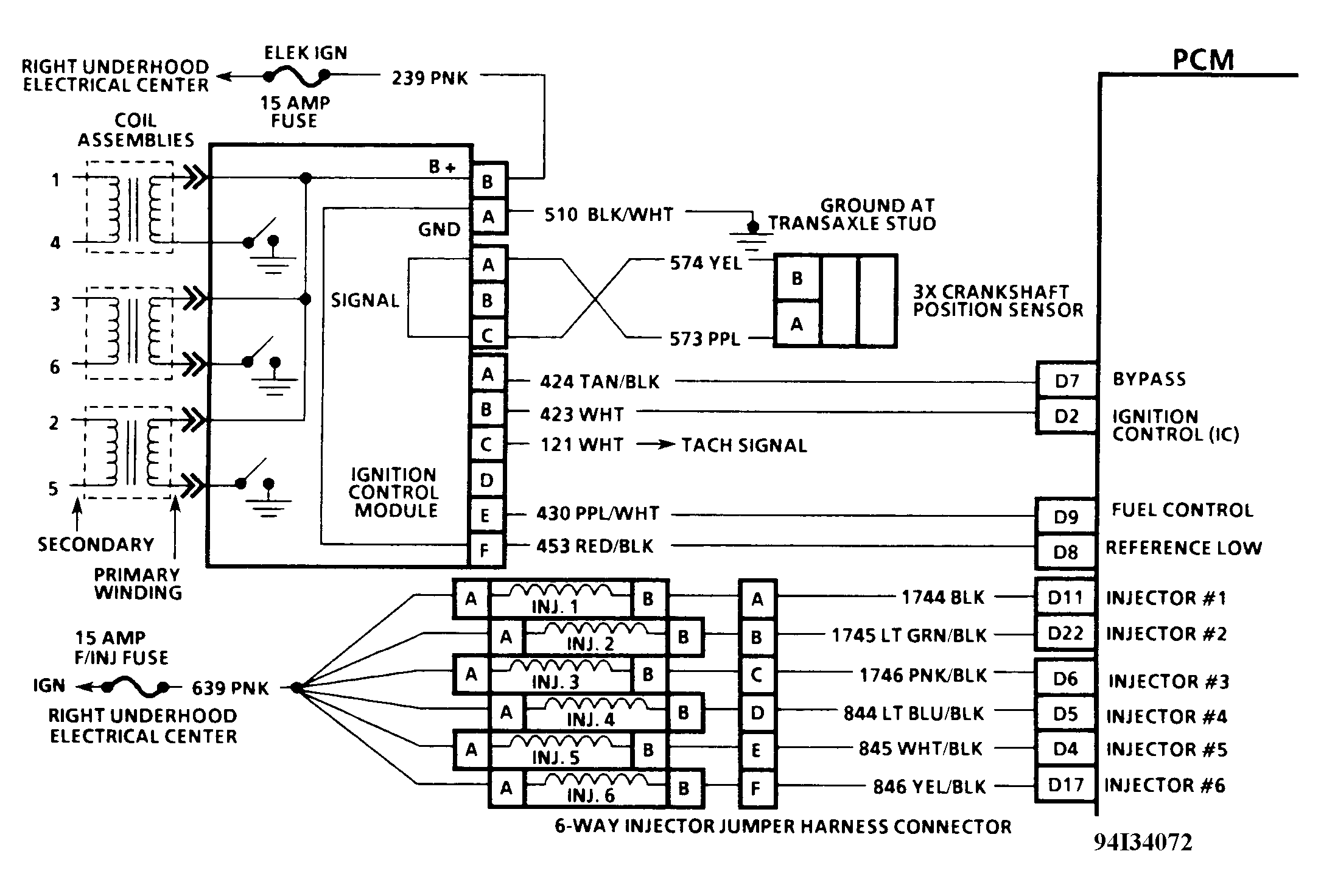 Courtesy of GENERAL MOTORS CORP.