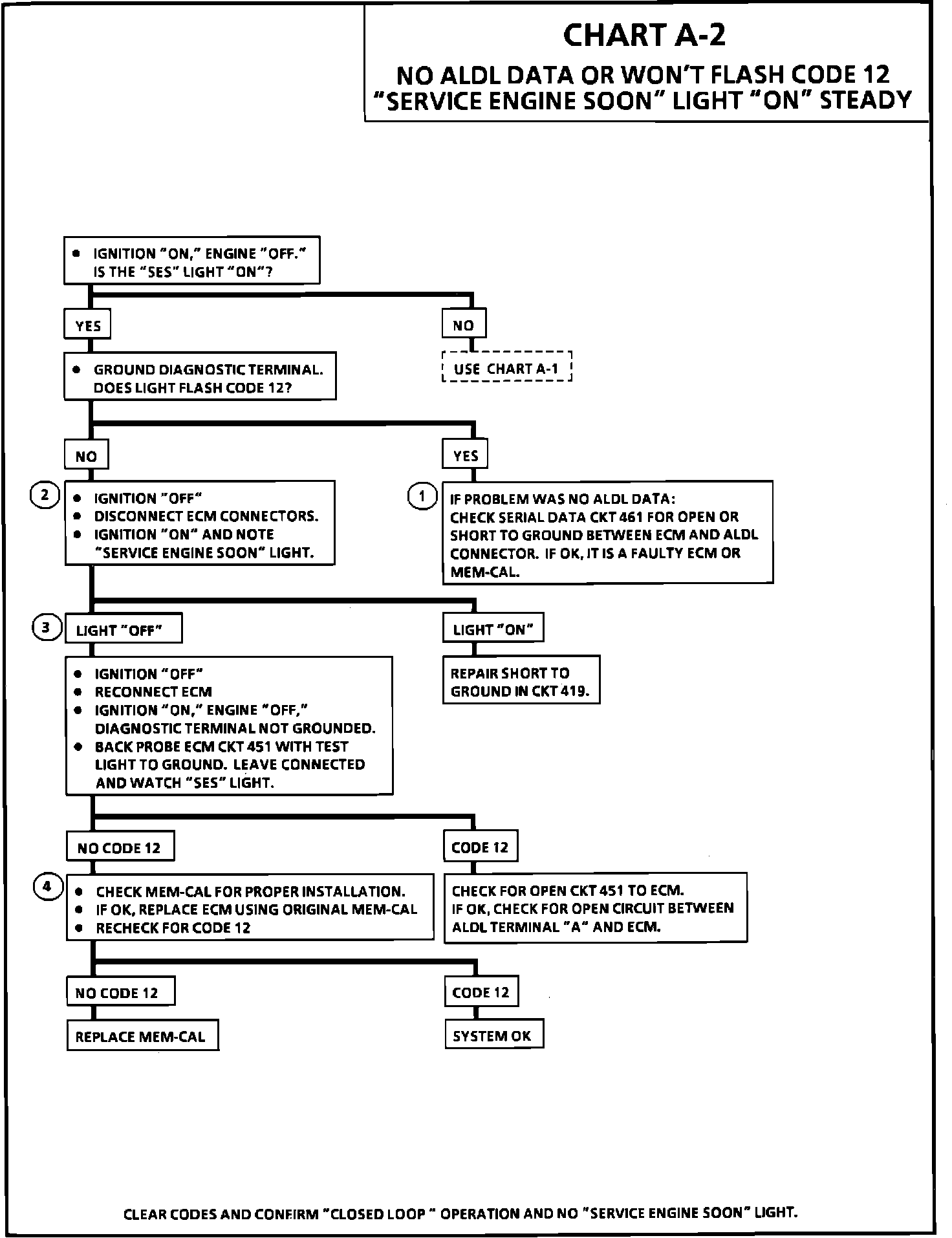
Chart A-2 Won't Flash DTC 12 No Serial Data MIL On Steady
Chart A-2:
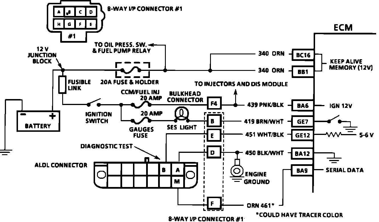
Wiring Diagram:
TEST DESCRIPTION: The numbers below refer to the circled numbers on the diagnostic chart.
1. A "SERVICE ENGINE SOON" light "ON" is a basic test to determine if there is a 12 volt supply and ignition 12 volts to the ECM. No ALDL may be due to an ECM problem and CHART A-2 will diagnose the ECM. If the TPS is over 2.5 volts the engine may be in clear flood mode which will cause starting problems. The engine will not start without reference pulses and therefore the "Scan" should read rpm (reference) during crank.
2. For the first two seconds with ignition ON or whenever reference pulses are received, PPSW should indicate the fuel pump circuit voltage (8 to 12 volts).
3. Because the direct ignition system two plugs and wires to complete the circuit of each coil, the opposite spark plug should be left connected. If rpm was indicated during crank, the ignition module is receiving a crank signal, but no spark at this test indicates the ignition module is not triggering the coils.
4. The test light should blink, Indicating the ECM is in control of the injectors. How bright the light blinks is not important. However, the test light should be a J 34730-3 or equivalent.
5. Use fuel pressure gauge J 34730-1 or equivalent. Wrap a shop towel around the fuel pressure tap to absorb any small amount of fuel leakage that may occur when installing the gauge.
6. This test will determine if the ignition module is not generating the reference pulse or if the wiring or the ECM are at fault. By touching and removing a test light to 12 volts on CKT 430, a reference pulse should be generated. If rpm is indicated, the ECM and wiring are OK.
7. This test will determine if the ignition module is not triggering the problem coil or if the tested coil is at fault. This test could also be performed by using another known good coil.