Sensors and Lead Wires
Fig. 29 ECM sensor circuit test connections:
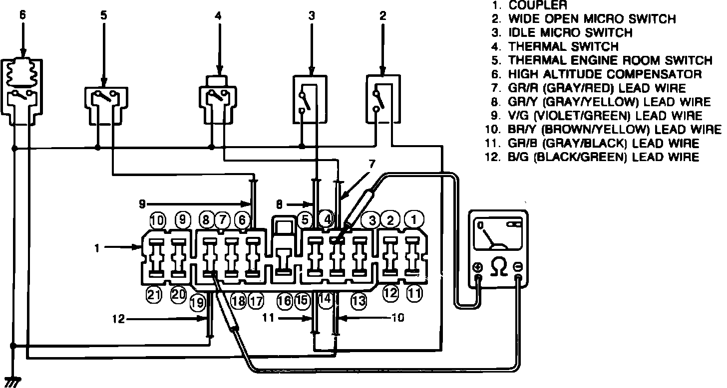
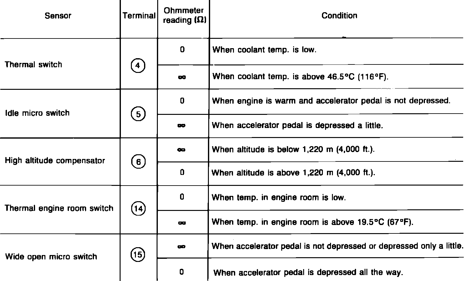
Fig. 30 ECM sensor circuit test specifications:
The feedback system uses the following sensors: wide open micro switch, idle micro switch, thermal switch, high altitude compensator and thermal engine compartment switch. If any of these sensors malfunction or if a sensor circuit is interrupted, the feedback system will not function properly since the ECM is not receiving a signal. Check each sensor and its circuit as follows:
1. Turn ignition off.
2. Disconnect ECM connector.
3. Connect ohmmeter between terminal 4 of ECM harness connector and terminal 19 (ground), Fig. 29, and measure resistance. Repeat with terminals 5, 6, 14, and 15.
4. Compare observed reading to Fig. 30.
5. Reconnect ECM connector securely.