- Disconnect the battery. BATTERY NEGATIVE CABLE DISCONNECTION AND CONNECTION
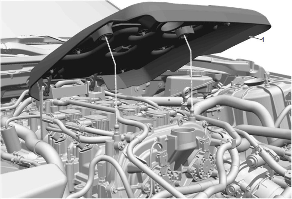
- Remove the oil fill cap.
 Courtesy of GENERAL MOTORS COMPANY Courtesy of GENERAL MOTORS COMPANY
|
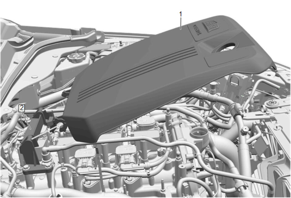
- Lift up on the front of the intake manifold cover (1).
 Courtesy of GENERAL MOTORS COMPANY Courtesy of GENERAL MOTORS COMPANY
|
- Intake Manifold Cover (1) @ Upper Intake Manifold Bracket (2) - Remove
 Courtesy of GENERAL MOTORS COMPANY Courtesy of GENERAL MOTORS COMPANY
|
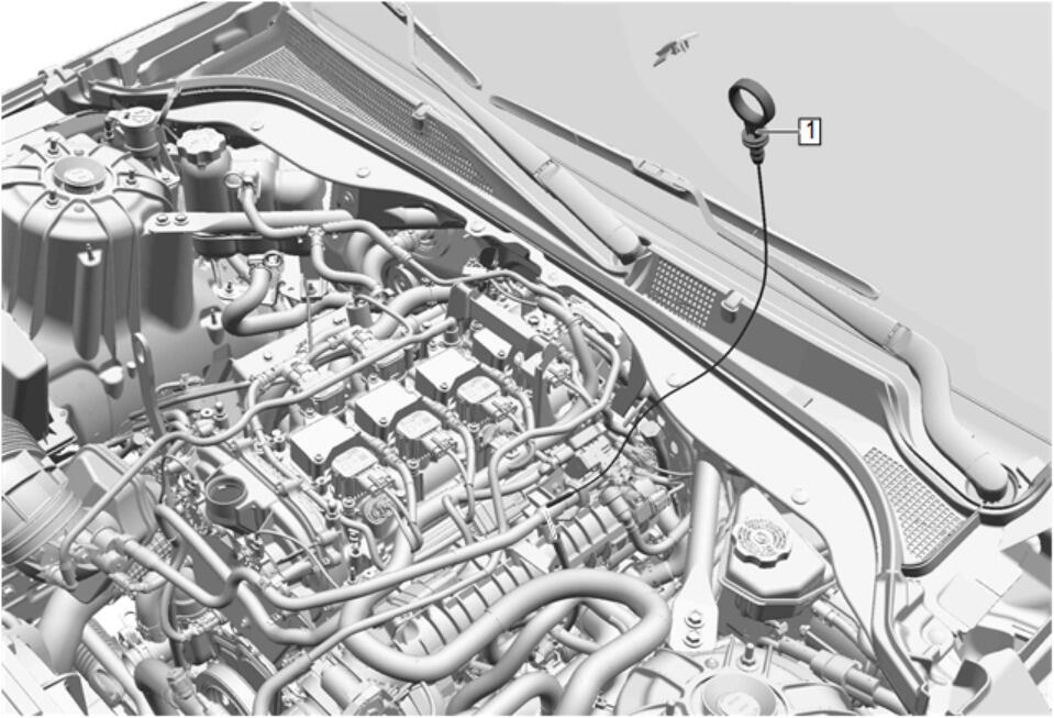
- Oil Level Indicator (1) - Remove
 Courtesy of GENERAL MOTORS COMPANY Courtesy of GENERAL MOTORS COMPANY
|
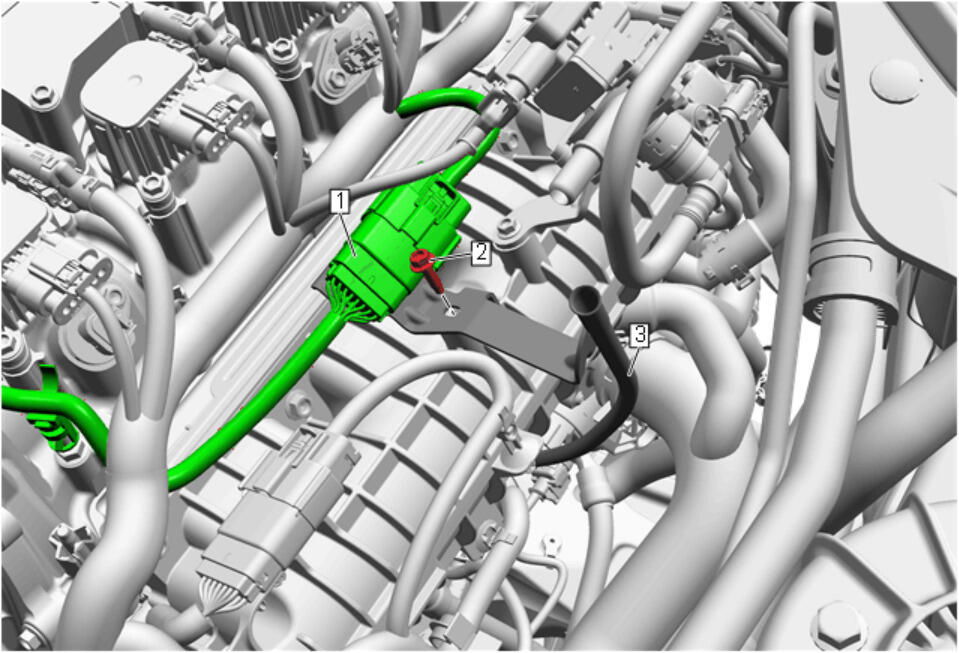
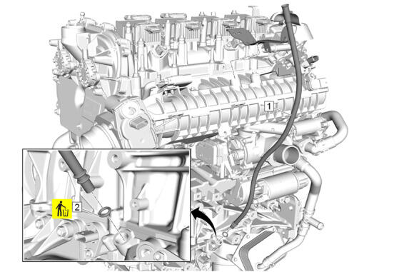
- Electrical Connector (1) @ Oil Level Indicator Tube (3) - Unclip
- Oil Level Indicator Tube Bracket Bolt (2) - Remove
 Courtesy of GENERAL MOTORS COMPANY Courtesy of GENERAL MOTORS COMPANY
|
- Oil Level Indicator Tube (1) - Remove
- Oil Level Indicator Tube Seal (2) - Remove and DISCARD
- Raise and support the vehicle. Lifting and Jacking the Vehicle
 Courtesy of GENERAL MOTORS COMPANY Courtesy of GENERAL MOTORS COMPANY
|
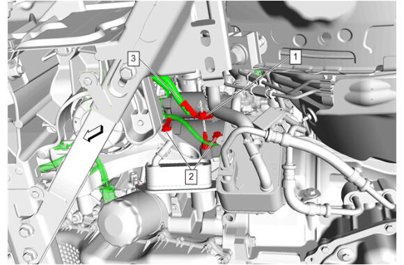
- Battery Negative Cable Nut (1) @ Starter Stud - Remove
- Engine Wiring Harness Retainer (2) - Disengage [2x]
- Auxiliary Generator Battery Jumper Cable (3) - Remove
 Courtesy of GENERAL MOTORS COMPANY Courtesy of GENERAL MOTORS COMPANY
|
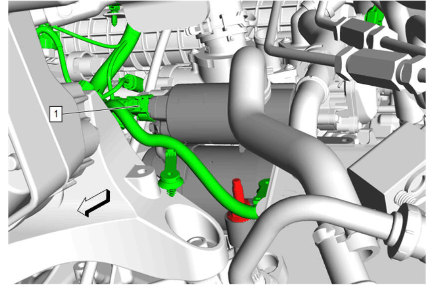
- Electrical Connector (1) - Disconnect
 Courtesy of GENERAL MOTORS COMPANY Courtesy of GENERAL MOTORS COMPANY
|
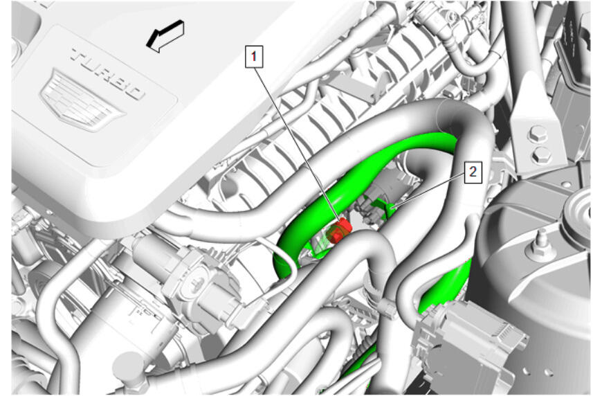
- Battery Positive Cable Nut (1) @ Starter Solenoid - Remove
- Auxiliary Generator Battery Jumper Cable (2) - Remove
 Courtesy of GENERAL MOTORS COMPANY Courtesy of GENERAL MOTORS COMPANY
|
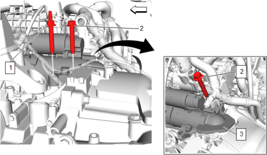
- Starter Stud (1) - Remove
- Starter Bolt (2) - Remove [2x]
- Starter (3) - Remove
 Courtesy of GENERAL MOTORS COMPANY Courtesy of GENERAL MOTORS COMPANY
|
- Install the EN-52476 Flywheel Lock and Alignment Tool (2) to the automatic transmission flexplate without the slide or timing pin engaged.
- Lower the vehicle.
 Courtesy of GENERAL MOTORS COMPANY Courtesy of GENERAL MOTORS COMPANY
|
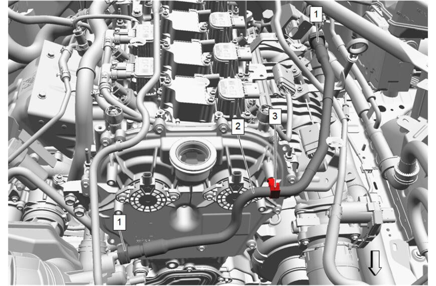
- Disconnect the evaporative emission canister purge tube quick disconnects (1). Plastic Collar Quick Connect Fitting Service
- Disconnect the evaporative emission canister purge tube (2) from the retainer (3).
 Courtesy of GENERAL MOTORS COMPANY Courtesy of GENERAL MOTORS COMPANY
|
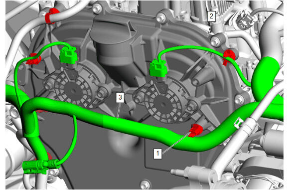
- Disconnect the 2 electrical connectors from the camshaft position actuator solenoids.
- Retainer (1) @ Timing Chain Upper Cover (2) - Unclip [6x]
- Engine Wiring Harness (3) - Reposition
 Courtesy of GENERAL MOTORS COMPANY Courtesy of GENERAL MOTORS COMPANY
|
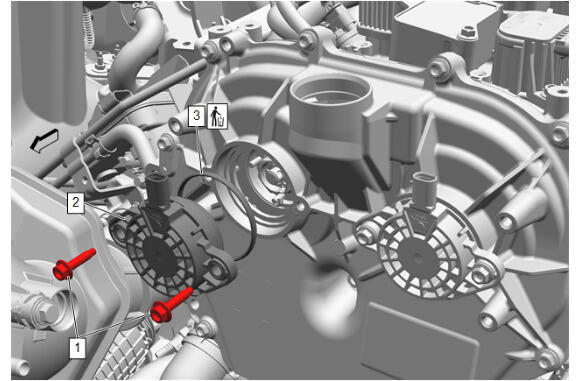
- Camshaft Position Actuator Valve Solenoid Bolt (1) - Remove [2x]
- Camshaft Position Actuator Valve Solenoid (2) - Remove
- Camshaft Position Actuator Magnet Gasket (3) - Remove and DISCARD
 Courtesy of GENERAL MOTORS COMPANY Courtesy of GENERAL MOTORS COMPANY
|
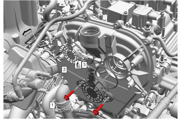
- Camshaft Position Actuator Valve Solenoid Bolt (1) - Remove [2x]
- Camshaft Position Actuator Valve Solenoid (2) - Remove
- Camshaft Position Actuator Magnet Gasket (3) - Remove and DISCARD
 Courtesy of GENERAL MOTORS COMPANY Courtesy of GENERAL MOTORS COMPANY
|
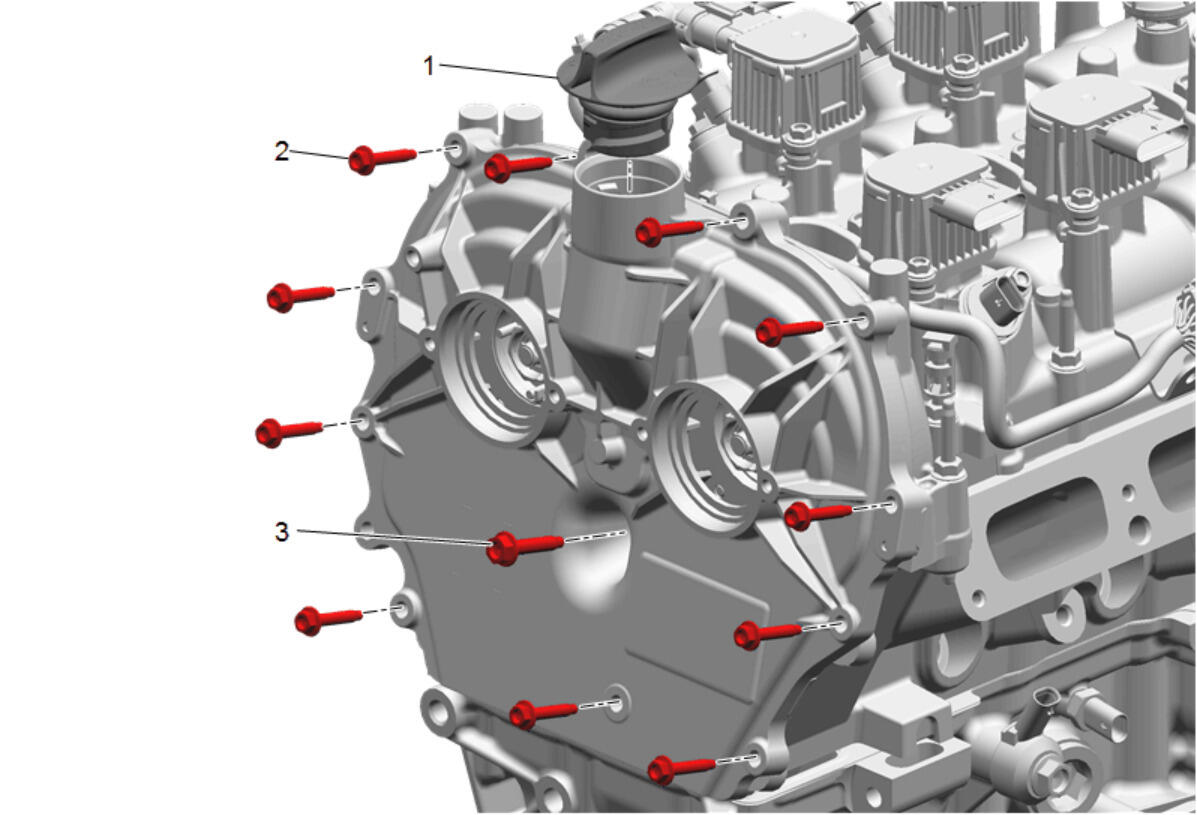
- Timing Chain Upper Cover Bolt Engine Front Cover Bolt - M6 (3) - Remove
- Timing Chain Upper Cover Bolt - M5 (2) - Remove [11x]
 Courtesy of GENERAL MOTORS COMPANY Courtesy of GENERAL MOTORS COMPANY
|
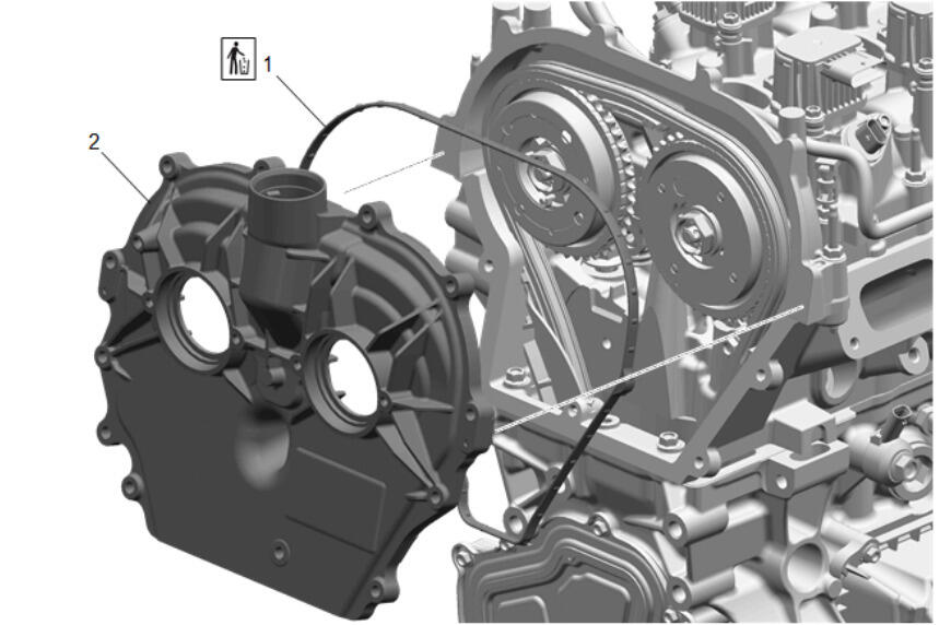
- Timing Chain Upper Cover (2) - Remove
- Timing Belt Front Upper Cover Seal (1) - Remove and DISCARD
 Courtesy of GENERAL MOTORS COMPANY Courtesy of GENERAL MOTORS COMPANY
|
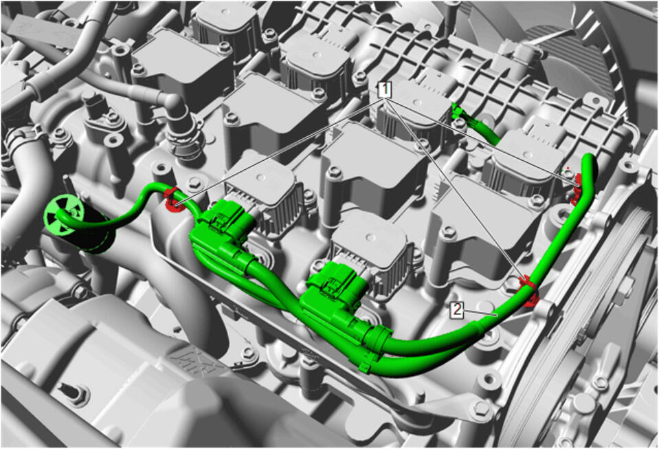
- Retainer (1) - Unclip [3x]
- Engine Wiring Harness (2) - Reposition
 Courtesy of GENERAL MOTORS COMPANY Courtesy of GENERAL MOTORS COMPANY
|
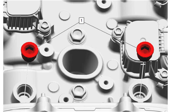
- Camshaft Cover Opening Plug (1) - Remove [2x]
 Courtesy of GENERAL MOTORS COMPANY Courtesy of GENERAL MOTORS COMPANY
|
NOTE:
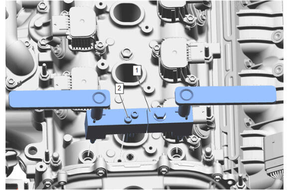
Rotate the engine using the crankshaft balancer until the locking pins of the EN-52462-A Camshaft Alignment Tool (1) drop into the slots in the camshafts.
- EN-52462-A Camshaft Alignment Tool (1) - Install
- Insert the bolt (2) of the EN-52462-A Camshaft Alignment Tool (1) into the camshaft carrier and tighten to secure the tool to the camshaft carrier.
 Courtesy of GENERAL MOTORS COMPANY Courtesy of GENERAL MOTORS COMPANY
|
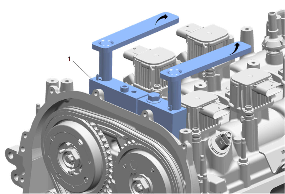
- Lock the EN-52462-A Camshaft Alignment Tool (1) by rotating the levers in direction of arrow.
Courtesy of GENERAL MOTORS COMPANY
|
NOTE:
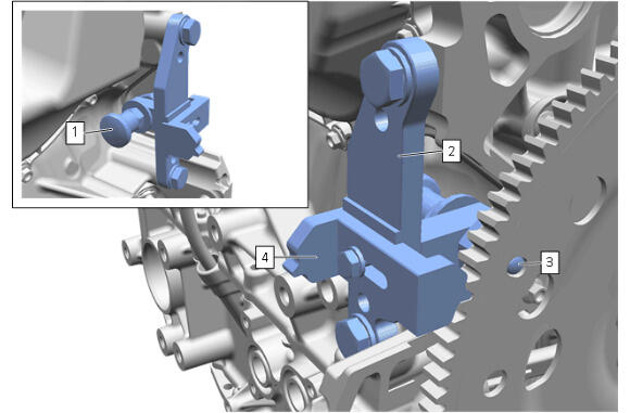
The timing pin (3) is installed into the flexplate for engine timing procedures, it can be damaged if torque is applied to the flexplate with the timing pin engaged. The timing pin must be placed in the retracted position using the handle (1) and twisting to locked position. The slide part (4) to be installed to the flexplate when torque is applied to the flexplate or crankshaft balancer bolt.
- Install the timing pin (3) by releasing the handle (1).
 Courtesy of GENERAL MOTORS COMPANY Courtesy of GENERAL MOTORS COMPANY
|
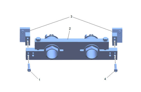
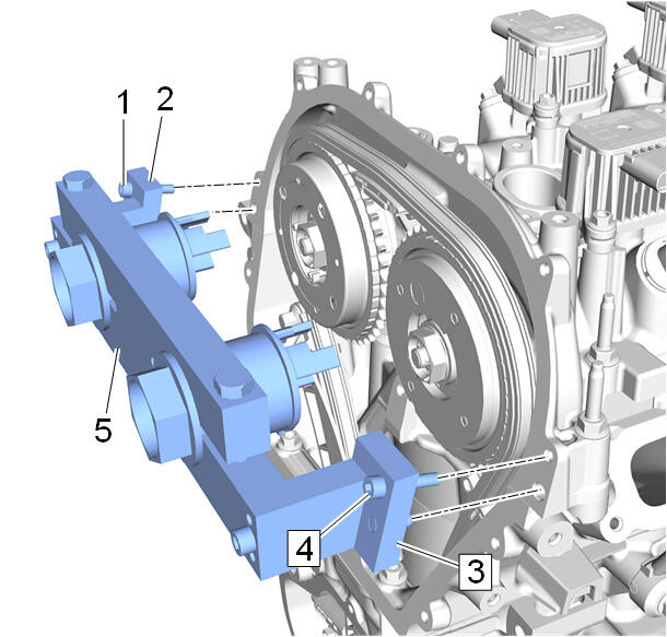
- Install the EN-52461 Cam Phaser Torque Reaction Tool (2) to the 2 EN-52461-100 Adapter Cam Phaser Torque Reaction Tool (3).
- Hand tighten the 2 bolts (1, 4) of EN-52461 Cam Phaser Torque Reaction Tool.
 Courtesy of GENERAL MOTORS COMPANY Courtesy of GENERAL MOTORS COMPANY
|
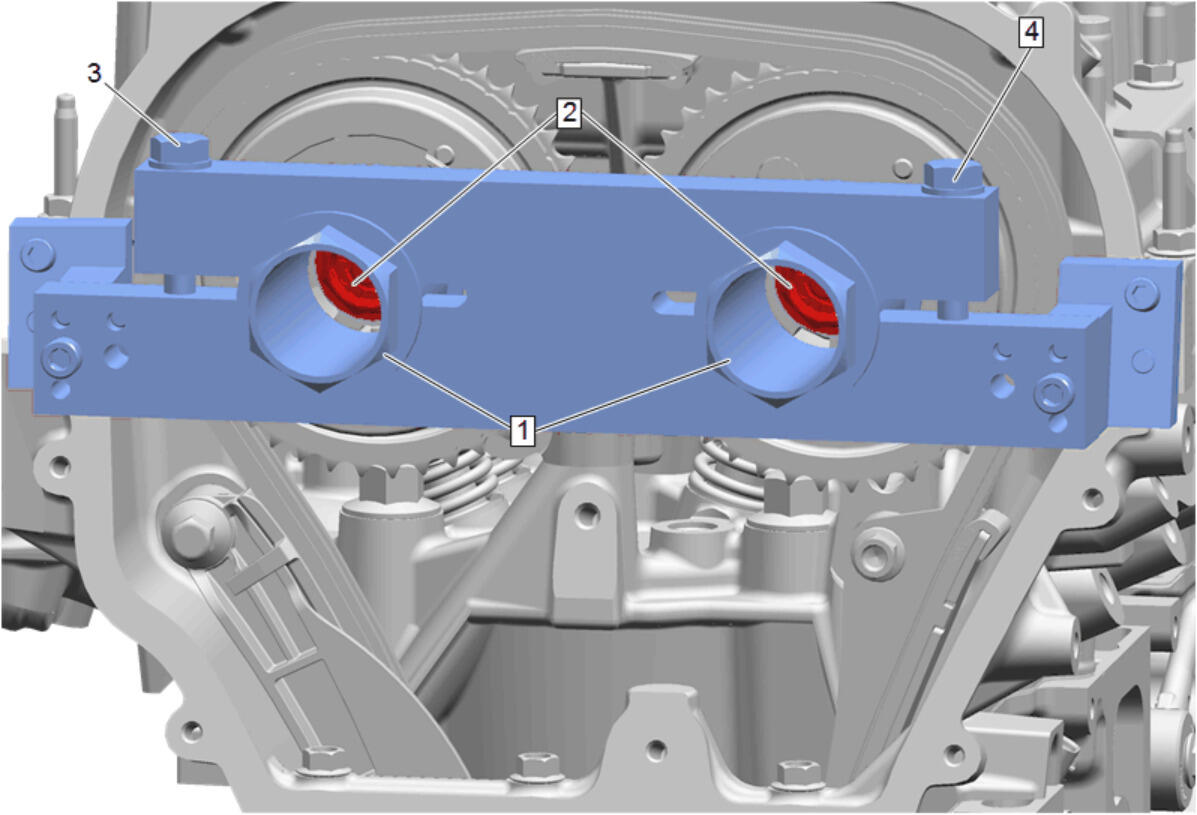
- Install the EN-52461 Cam Phaser Torque Reaction Tool (5) along with the 2 EN-52461 Cam Phaser Torque Reaction Tool (2, 3) to the camshaft carrier.
- Tighten the 2 bolts (1, 4) of EN-52461-100 Adapter Cam Phaser Torque Reaction Tool.
- Tighten the 2 bolts from the EN-52461 Cam Phaser Torque Reaction Tool to the 2 EN-52461 Cam Phaser Torque Reaction Tool that were hand tightened.
 Courtesy of GENERAL MOTORS COMPANY Courtesy of GENERAL MOTORS COMPANY
|
- Install the EN-52461-1 Holder (1) to the holes in the camshaft sprocket.
- Check that the EN-52461-1 Holder (1) sits correctly in the hole of the camshaft sprocket.
- Loosen the specific camshaft sprocket bolt (2) for the side that is being replaced. To take tension off the actuator that is required for the specific camshaft bolt, use steps below.
NOTE:
Only do the side that is being replaced.
- Turn the exhaust side counter clockwise to 6 N.m (53 lb in) and tighten bolt (3) just enough to hold the EN-52461-1 Holder in place.
- Turn the intake side counter clockwise to 6 N.m (53 lb in) and tighten bolt (4) just enough to hold the EN-52461-1 Holder in place.
 Courtesy of GENERAL MOTORS COMPANY Courtesy of GENERAL MOTORS COMPANY
|
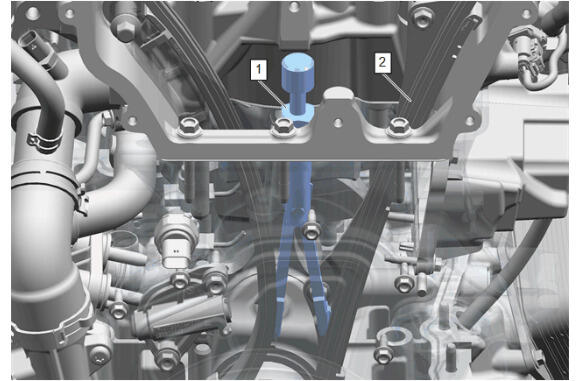
- Install the EN-52436 Timing Chain Tensioner Retention Tool (1) at the timing chain (2) down far enough to hold pressure against the tensioner to hold it in place.
 Courtesy of GENERAL MOTORS COMPANY Courtesy of GENERAL MOTORS COMPANY
|
NOTE:
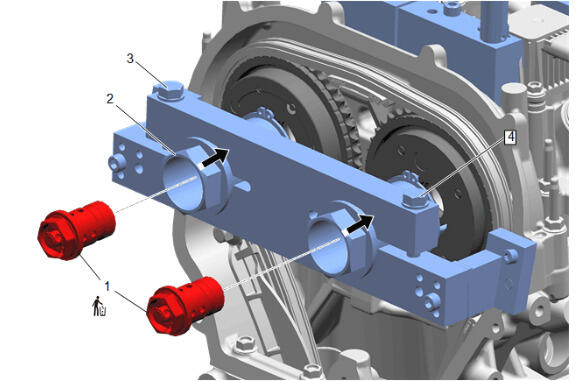
Remove and DISCARD the one camshaft sprocket bolt that is required.
- Camshaft Sprocket Bolt (1) - Remove and DISCARD