Vacuum Brake Booster: Service and Repair
Power Vacuum Brake Booster Replacement
Removal Procedure
Caution: Refer to Battery Disconnect Caution .
1. Disconnect the battery negative cable. Refer to Battery Negative Cable Disconnection and Connection (Service and Repair) .
2. Remove the coolant surge tank. Refer to Radiator Surge Tank Replacement (Service and Repair) .
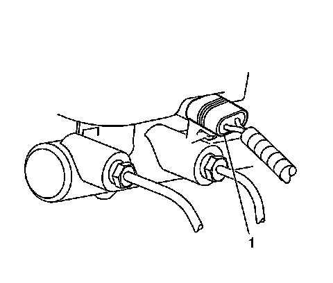
3. Disconnect the electrical connector (1) from the brake fluid level sensor.
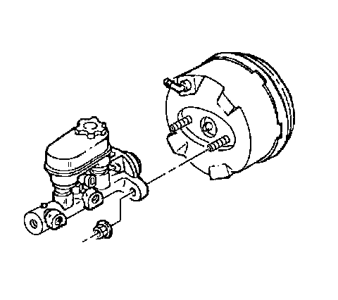
4. Remove the nuts securing the master cylinder to the brake booster.
5. Remove the master cylinder from the brake booster without disconnecting the brake pipes and position the master cylinder aside.
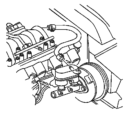
6. Disconnect the brake booster vacuum hose from the booster check valve.
7. Remove the instrument panel lower trim panel. Refer to Driver Knee Bolster Panel Replacement (Service and Repair) .
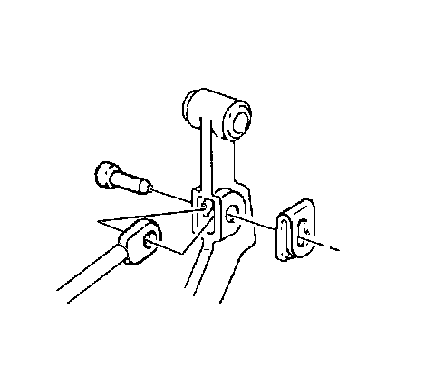
8. Remove the retainer, washer, brake pedal pin, and brake booster pushrod from the brake pedal.
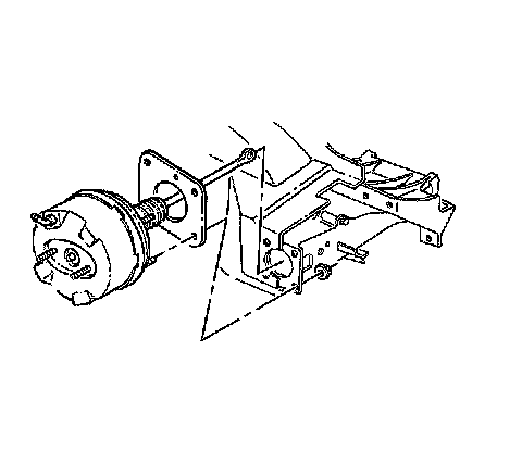
9. Remove the brake booster mounting nuts and washers from the booster studs.
Important: The brake booster is retained to the cowl with push-on nuts.
10. In order to remove the booster from the cowl, perform the following steps:
* In order to release the booster mounting studs from the push-on nuts, move booster from side to side.
* Pull the booster straight out.
11. Remove the brake booster and seal from the cowl.
12. Inspect the booster seal and sealing surfaces for damage. Replace the seal if necessary.
Installation Procedure
1. Install the seal and brake booster to the front of dash.
Notice: Refer to Fastener Notice (Fastener Notice) .
2. Install brake booster mounting nuts and washers to the booster studs.
Tighten the brake booster mounting nuts to 27 N.m (19 lb ft).
3. Install the brake booster pushrod, brake pedal pin, washer, and retainer to the brake pedal. Verify proper engagement of the retainer to the brake pedal by rotating the retainer.
4. Install the instrument panel lower trim panel. Refer to Driver Knee Bolster Panel Replacement (Service and Repair) .
5. Connect the brake booster vacuum hose to the brake booster check valve.
6. Install the master cylinder to the brake booster.
7. Install the master cylinder mounting nuts.
Tighten the master cylinder mounting nuts to 29 N.m (21 lb ft).
8. Connect the electrical connector (1) to the brake fluid level sensor.
9. Install the coolant surge tank. Refer to Radiator Surge Tank Replacement (Service and Repair) .
10. Connect the battery negative cable. Refer to Battery Negative Cable Disconnection and Connection (Service and Repair) .
11. Program the transmitters. Refer to Transmitter Programming (N. America and Japan, except Canada) (Programming and Relearning)Transmitter Programming (Canada and Europe) (Programming and Relearning) .