Power Vacuum Brake Booster Replacement (RHD)
Power Vacuum Brake Booster Replacement (RHD)
Special Tools
J 22805-B Brake Booster Holder
Removal Procedure
1. Remove the right side instrument panel insulator panel. Refer to Instrument Panel Insulator Panel Replacement - Right Side (Service and Repair) .
2. Without disconnecting the steering column from the intermediate shaft, lower the steering column assembly and support the column. Refer to Steering Column Replacement (without JL7) (Steering Column Replacement (without JL7))Steering Column Replacement (with JL7) (Steering Column Replacement (with JL7)) .
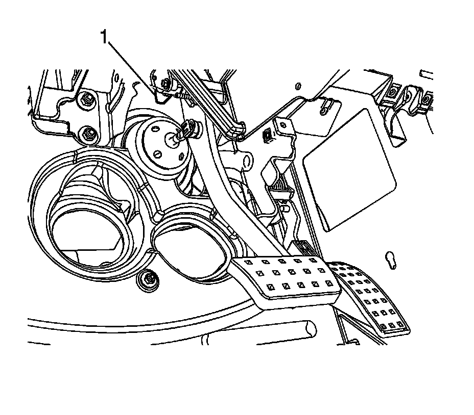
3. Disconnect the brake pedal position sensor (1) electrical connector.
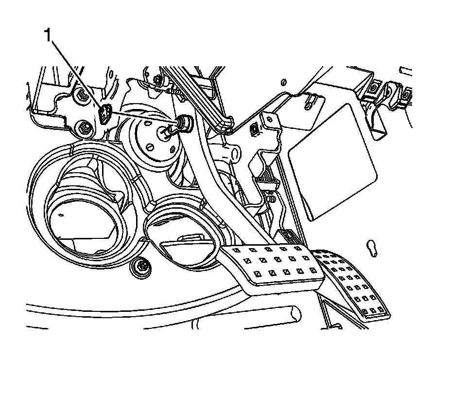
4. Remove the vacuum brake booster pushrod retaining clip (1).
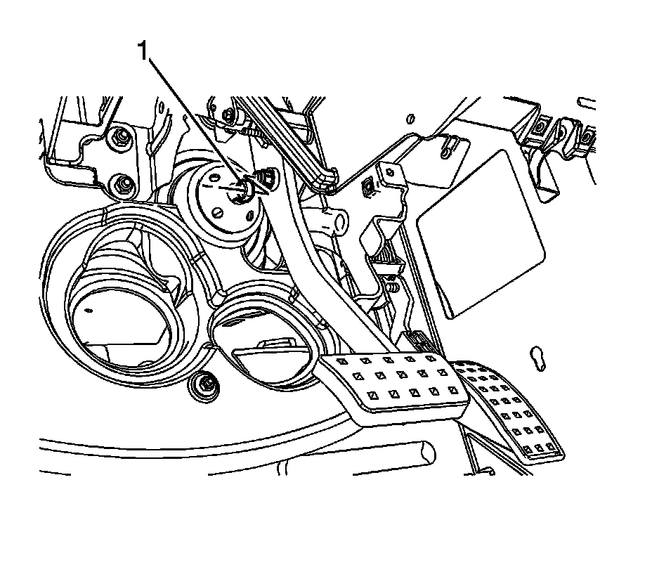
5. Disconnect the vacuum brake booster pushrod (1) from the brake pedal pivot.
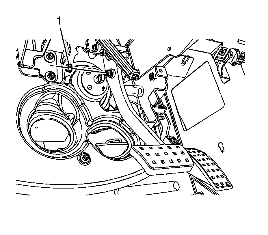
6. Remove the vacuum brake booster pushrod bushing (1).
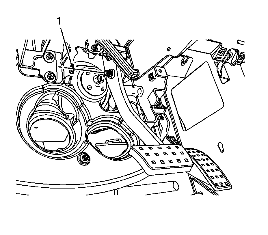
7. Remove the vacuum brake booster pushrod wave washer (1).
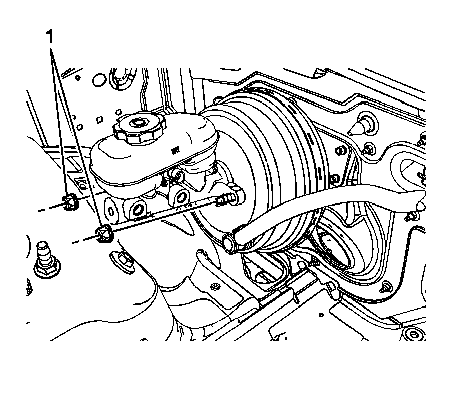
8. Remove the cross vehicle brace, if equipped. Refer to Cross Vehicle Brace Replacement (DX) (Cross Vehicle Brace Replacement (DX)) .
9. Disconnect the master cylinder fluid level sensor electrical connector.
10. Remove the master cylinder nuts (1).
11. Without disconnecting the brake pipes, position aside the master cylinder and support with heavy mechanics wire or equivalent.
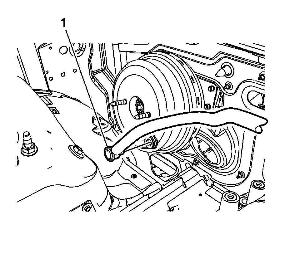
12. Disconnect the vacuum brake booster check valve and hose assembly (1) and position aside.
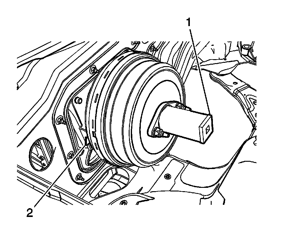
13. Install the J 22805-B (1) to the vacuum brake booster and secure with the master cylinder nuts.
14. Using a flat-bladed tool, depress the locking tab (2) toward the cowl.
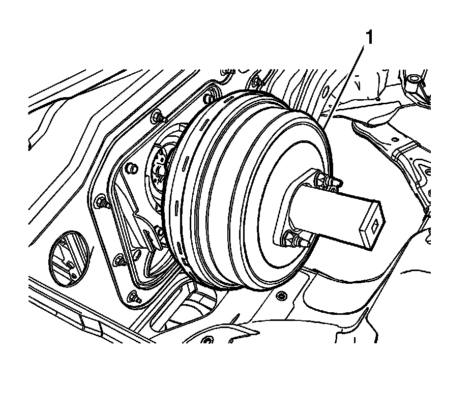
15. Rotate the J 22805-B and vacuum brake booster (1) counterclockwise to release the vacuum brake booster from the bracket.
Important: Do not attempt to remove the vacuum brake booster completely. The vacuum brake booster pushrod retaining clip must be released prior to booster removal.
16. Carefully pull the vacuum booster forward slightly and support the vacuum booster to access the booster pushrod retaining clip.
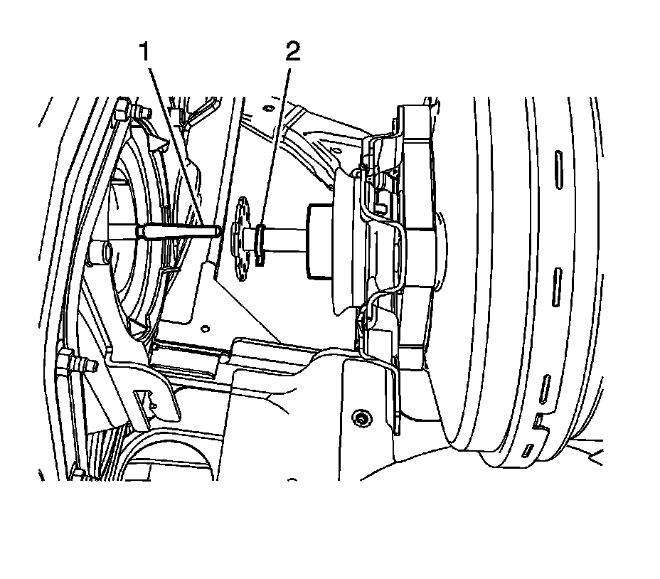
17. Compress the vacuum brake booster foam filter to access the vacuum brake booster pushrod retaining clip.
18. Disconnect the brake booster pushrod (1) from the booster by releasing the retaining clip (2).
19. Remove the vacuum brake booster from the vehicle.
20. Remove the vacuum brake booster pushrod through the dust boot from inside of the vehicle, if necessary.
Installation Procedure
Notice: Internal components of this booster are not serviceable. The housing must not be unstaked and separated. Separating the housing will cause permanent deformation, preventing the booster from holding proper volume.
Notice: Inspect the locking flanges on booster and mounting plate. Replace the booster and mounting plate if the locking flanges are bent or damaged.
1. Install the vacuum brake booster pushrod through the dust boot from inside of the vehicle, if removed.
2. Install the vacuum brake booster to the vehicle.
3. Compress the vacuum brake booster foam filter to access the vacuum brake booster pushrod retaining clip.
4. Connect the brake booster pushrod (1) to the booster and engage the retaining clip (2).
5. Position the vacuum brake booster (1) to the booster bracket.
6. Using the J 22805-B (1), rotate the vacuum booster clockwise until the locking tab (2) engages the cowl flange.
Ensure the booster locking tab fully engages in the bracket.
7. Remove the J 22805-B from the vacuum brake booster and discard the master cylinder nuts.
8. Install the vacuum brake booster check valve and hose assembly (1).
9. Install the master cylinder to the vacuum brake booster.
Notice: Refer to Fastener Notice (Fastener Notice) .
10. Install new master cylinder nuts (1).
Tighten the nuts to 25 N.m (18 lb ft).
11. Connect the master cylinder fluid level sensor electrical connector.
12. Install the cross vehicle brace, if equipped. Refer to Cross Vehicle Brace Replacement (DX) (Cross Vehicle Brace Replacement (DX)) .
13. Install the vacuum brake booster pushrod wave washer (1).
14. Install the vacuum brake booster pushrod bushing (1).
15. Connect the vacuum brake booster pushrod (1) to the brake pedal pivot.
16. Install the vacuum brake booster pushrod retaining clip (1).
17. Connect the brake pedal position sensor (1) electrical connector.
18. Install the steering column assembly. Refer to Steering Column Replacement (without JL7) (Steering Column Replacement (without JL7))Steering Column Replacement (with JL7) (Steering Column Replacement (with JL7)) .
19. Calibrate the brake pedal position sensor. Refer to Brake Pedal Position Sensor Calibration (Programming and Relearning) .
20. Install the right side instrument panel insulator panel. Refer to Instrument Panel Insulator Panel Replacement - Right Side (Service and Repair) .