Center Support: Service and Repair
Propeller Shaft Center Support Bearing Overhaul
Tools Required
* J 25863 Pinion Cone and Side Bearing Installer
* J 22912-01Split-Plate Bearing Puller
Removal Procedure
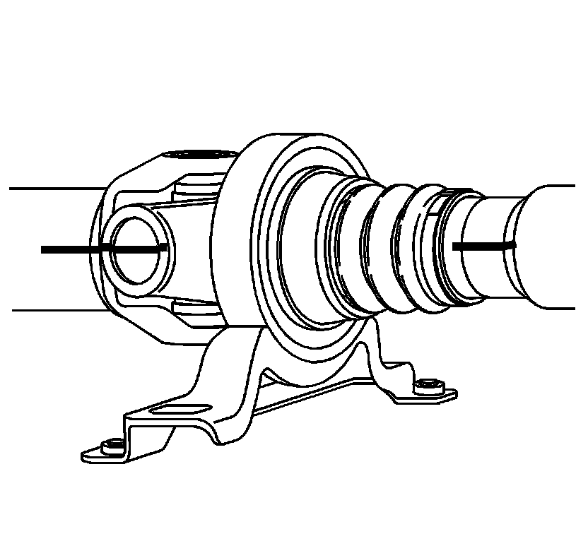
Notice: Never clamp propeller shaft tubing in a vise. Clamping propeller shaft tubing in a vise could dent or deform the tube causing an imbalance or unsafe condition. Always clamp on one of the yokes and support the shaft horizontally.
Important: Proper alignment on assembly is critical in order to maintain correct balance.
1. Using a paint stick, mark the shaft on both sides. The splines are not keyed, therefore, alignment marks are necessary for assembly.
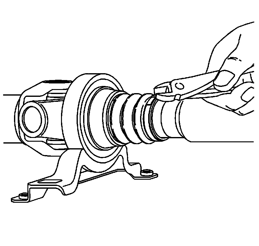
Important: The clamp is not reusable.
2. Remove the clamp holding the dust boot to the shaft. Discard the clamp.
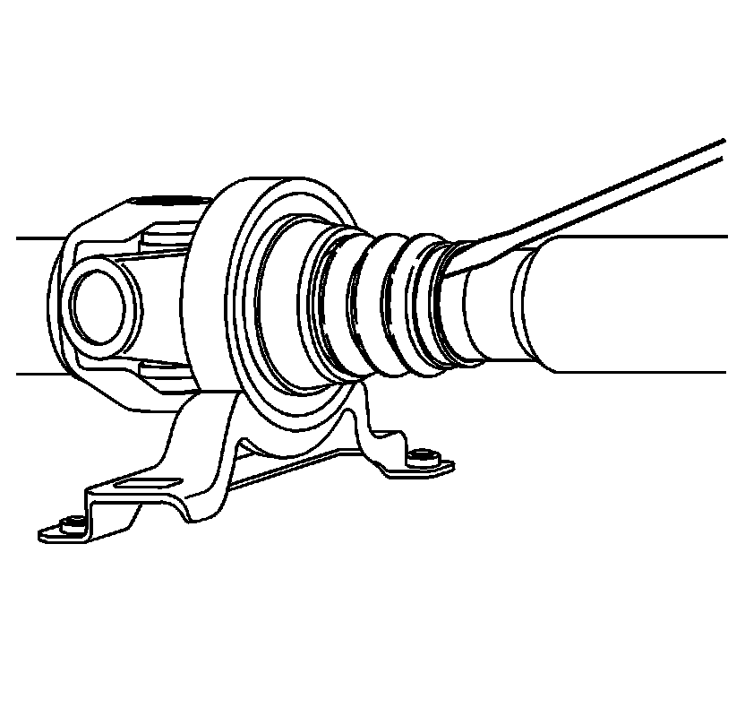
3. Pry the dust boot off the shaft tube.
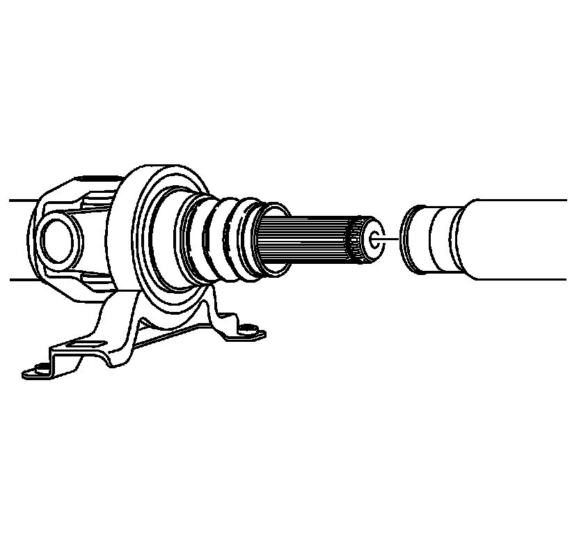
4. Hold the shaft on both sides of the bearing and pull or separate the 2 halves.
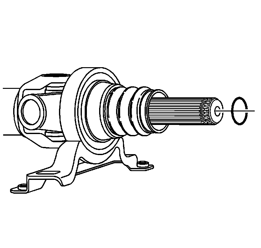
5. Remove the O-ring from the end of the spline shaft.
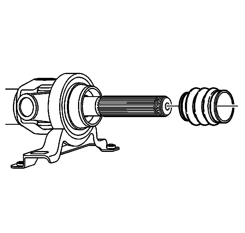
6. Remove the dust boot.
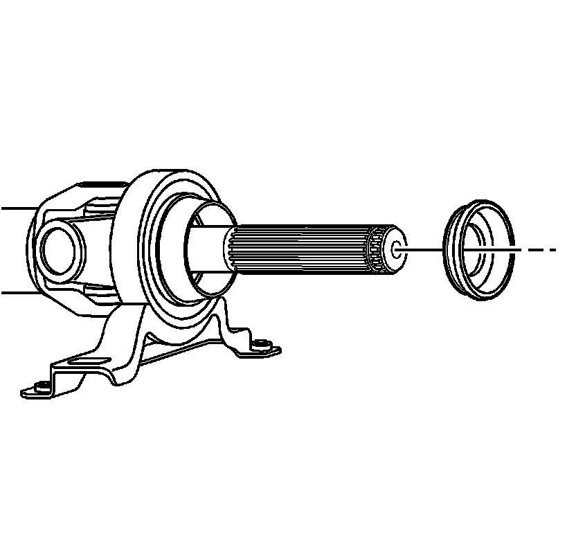
Important: Do not reuse the slinger.
7. Pry off the bearing slinger from the spline shaft. Discard the slinger.
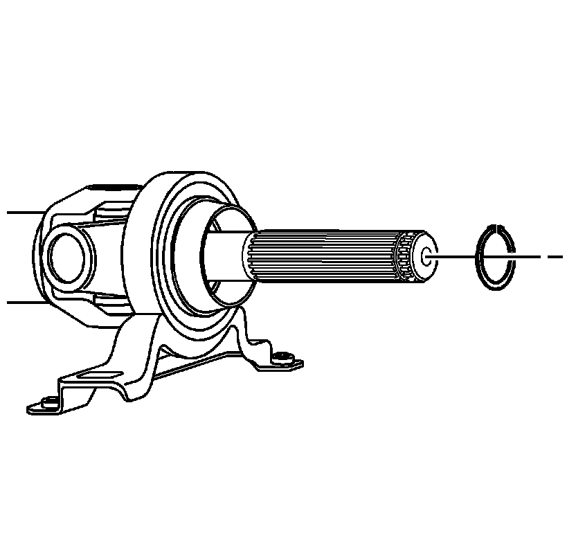
Important: Grease may have to be removed to see the snap ring.
8. Remove the snap ring from the groove.
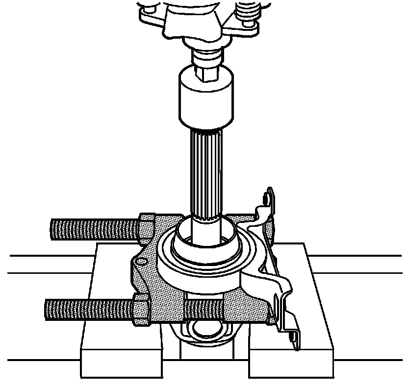
9. Install the J 22912-01 around the shaft behind the bearing. Place shaft in a press and remove the bearing.
Clean and Inspect
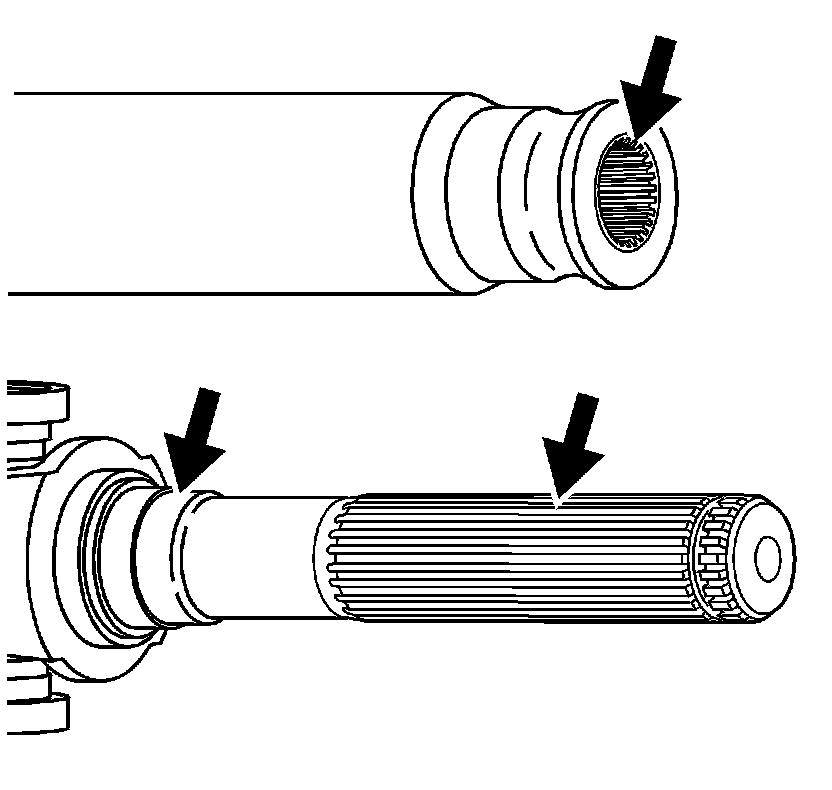
1. Clean grease from the splines on both halves of the shaft.
2. Remove any corrosion or debris from the bearing area.
Installation Procedure
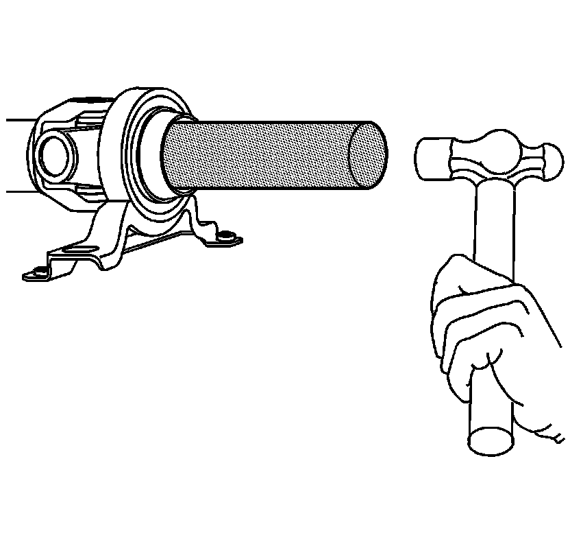
1. Slide a NEW bearing over the spline shaft.
2. Using the J 25863, drive on the bearing until it seats and the snap ring groove is visible.
3. Install a NEW snap ring in the groove.
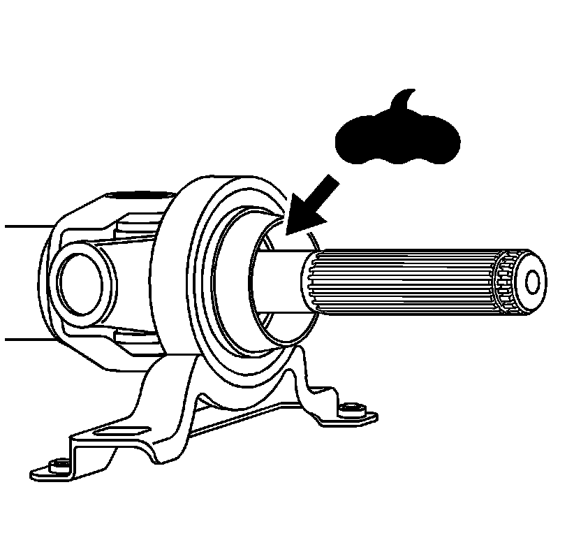
4. Apply 5-6 grams (0.18-0.21 oz) of grease from the kit in the snap ring area, ensuring that the surface of the bearing is covered.
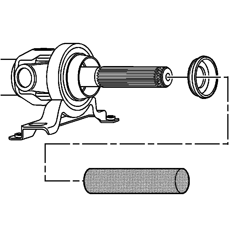
5. Install a NEW slinger from kit with the J 25863 until it seats on the shaft against the bearing.
6. Apply 1 gram (0.03 oz) of grease to the inside of the dust boot.
7. Slide the dust boot over the splines with the clamp end out.
8. Install the NEW O-ring on the end of the spline shaft.
9. Apply 1-2 grams (0.03-0.07 oz) of grease to the splines for assembly.
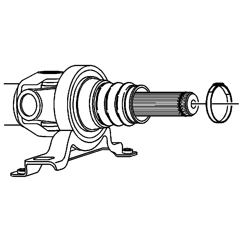
10. Install the NEW dust boot clamp over the splines.
11. Align the paint marks on the shaft to ensure proper assembly balance. Push the splines together.
12. Push the dust boot and clamp over the shaft.
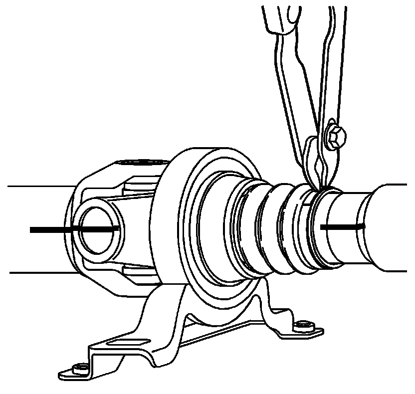
13. Compress the dust boot retaining clamp.