Wheel Drive Shaft Replacement - Front (Right)
Wheel Drive Shaft Replacement - Front (Right)
Tools Required
^ J2619-O1 Slide Hammer With Adapter
^ J29794 Extension
^ J44394 Seal Protector
^ J45341 Axle Shaft Puller
^ J45859 Wheel Hub Remover
Removal Procedure
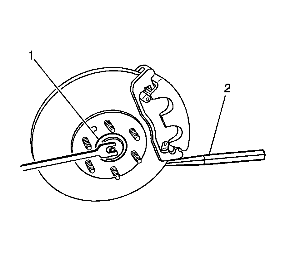
1. Raise and support the vehicle. Refer to Vehicle Lifting.
2. Remove the right front tire and wheel assembly.
3. Disconnect the right outer tie rod end from the steering knuckle. Do NOT loosen the tie rod end jam nut.
4. Insert a drift or punch (2) into the brake rotor and against the brake caliper mounting bracket, in order to prevent the wheel hub and bearing from turning.
5. Remove and discard the right front wheel drive shaft spindle nut (1) retaining the wheel drive shaft to the hub.
Important: The wheel drive shaft spindle nut must not be reused. Replace the wheel drive shaft spindle nut with a new nut whenever it is removed.
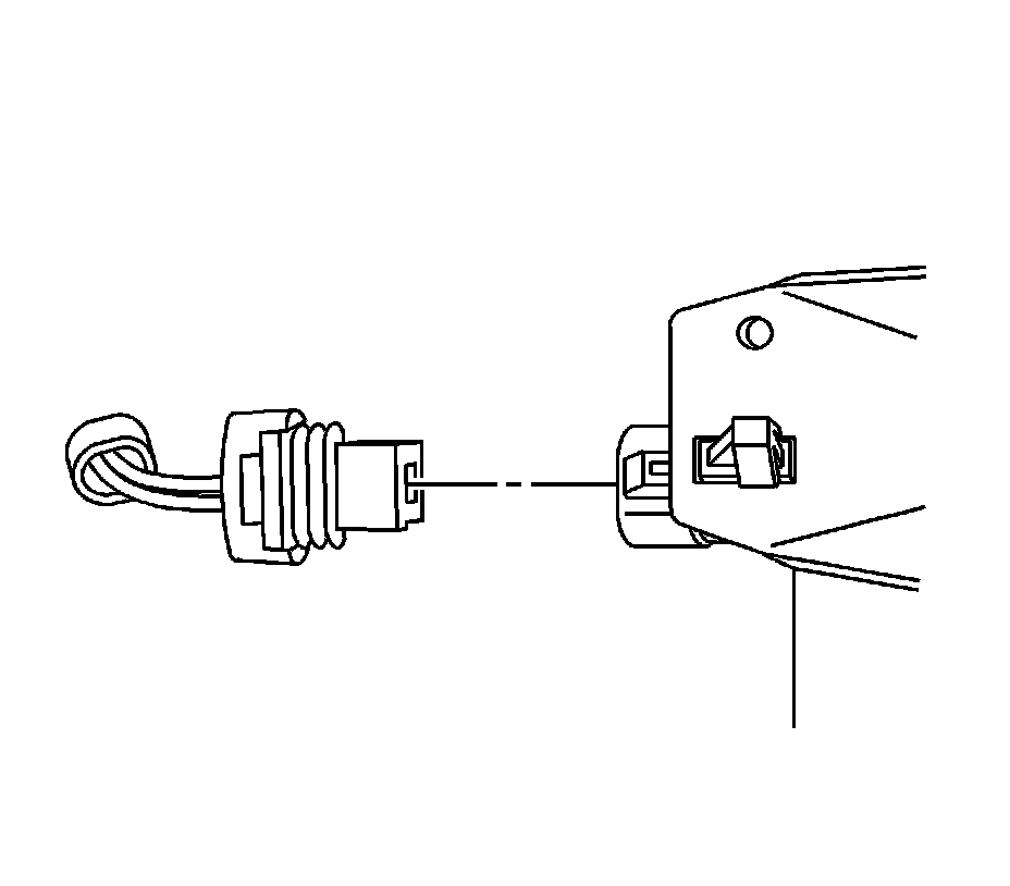
6. Disconnect the electrical connector from the wheel speed sensor and reposition the wiring harness away from the ball joint.
Important: Be sure that the wheel speed sensor wiring harness is repositioned away from the ball joint, after disconnecting the electrical connector from the sensor.
7. Disconnect the right upper ball joint from the steering knuckle.
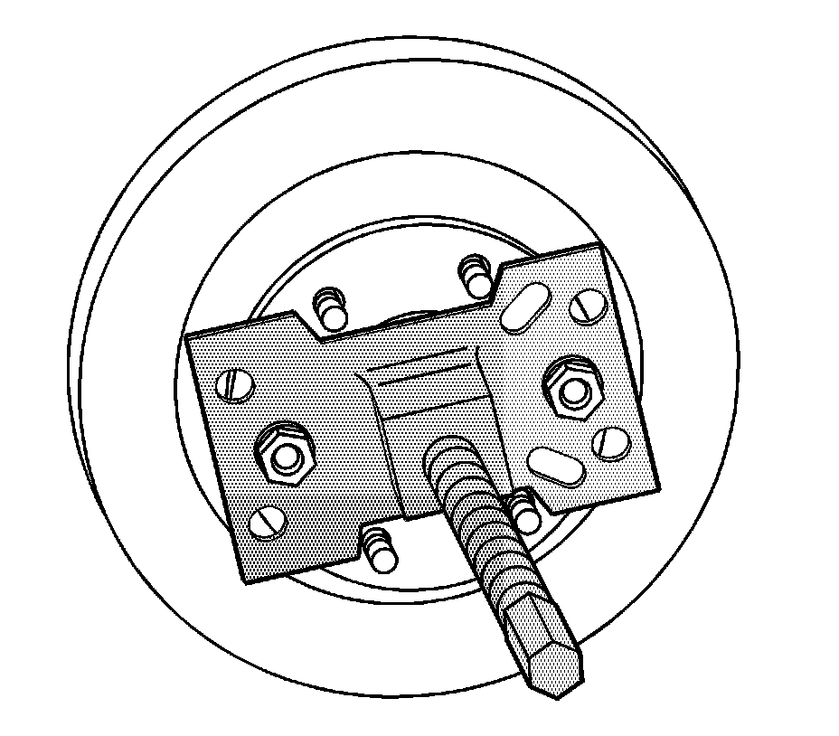
8. Install the J45859 or equivalent onto the wheel hub and secure with wheel nuts.
Important: Be sure to support the wheel drive shaft until it is fully removed from the vehicle.
9. Using the J45859 or equivalent, disengage the right front wheel drive shaft from the wheel hub and bearing and support the wheel drive shaft.
10. Remove J45859 or equivalent from the wheel hub.
11. Assemble the J2619-O1, the J29794, and the J45341.
12. Install J45341 to the wheel drive shaft inner joint pull groove.
13. Using the J2619-O1, the J29794, and the J45341, disengage the wheel drive shaft from the differential enough to install J44394.
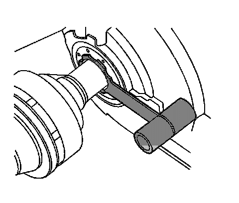
14. Carefully install the J44394 over the wheel drive shaft.
Notice: J-44394 must be installed into the differential output shaft seal prior to removing and installing the wheel drive shaft. Failure to install J-44394 as indicated may cause the splines of the wheel drive shaft to cut the differential output seal.
15. Carefully slide the J44394 into the differential output shaft seal.
16. Remove the wheel drive shaft from the vehicle.
17. Remove the J2619-O1, the J29794, and the J45341 from the wheel drive shaft inner joint.
18. Remove and discard the wheel drive shaft retaining ring from the retaining ring groove. The wheel drive shaft retaining ring is on the splined shaft of the inner joint housing.
Installation Procedure
1. Install the new wheel drive shaft retaining ring to the retaining ring groove. The wheel drive shaft retaining ring is on the splined shaft of the inner joint housing.
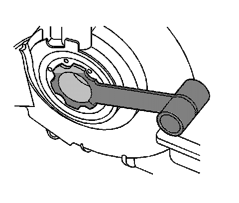
2. If previously removed, carefully install J44394 into the differential output shaft seal.
Notice: J-44394 must be installed into the differential output shaft seal prior to removing and installing the wheel drive shaft. Failure to install J-44394 as indicated may cause the splines of the wheel drive shaft to cut the differential output seal.
3. Carefully install the wheel drive shaft into the differential until the splines are past the J44394.
Important: In order to prevent lubricant leaks, use care when installing the wheel drive shaft to the differential. Do not damage the oil seal. Replace the oil seal if it becomes nicked, distorted, or is otherwise damaged.
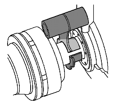
4. Carefully remove the J44394 from the differential output shaft seal.
5. Carefully continue installing the wheel drive shaft into the differential until the retaining ring is fully seated.
6. Verify that the wheel drive shaft is properly engaged to the differential by grasping the inner joint housing and pulling outward. Do not pull on the wheel drive shaft bar. The wheel drive shaft will remain firmly in place when properly engaged.
7. Install the right front wheel drive shaft to the hub and bearing.
8. Connect the right upper ball joint to the steering knuckle.
9. Connect the wheel speed sensor electrical connector.
10. Loosely install the NEW wheel drive shaft spindle nut.
Important: Ensure that the drive shaft seals do not have any abrasions, cuts or punctures.
11. Insert a drift or punch (1) into the rotor and against the caliper mounting bracket in order to prevent the hub and bearing from turning.
12. Use the New wheel drive shaft spindle nut to slowly pull the spindle to the wheel hub and bearing assembly.
Tighten the wheel drive shaft spindle nut to 160 Nm (118 ft. lbs.).
Notice: Refer to Fastener Notice in Service Precautions.
13. Remove the drift or punch from the rotor.
14. Connect the outer tie rod end to the steering knuckle.
15. Install the tire and wheel assembly.
16. Lower the vehicle.