Control Valve Lower Body and Upper Body Replacement
WARNING: This page is about a different variant/trim than selected.
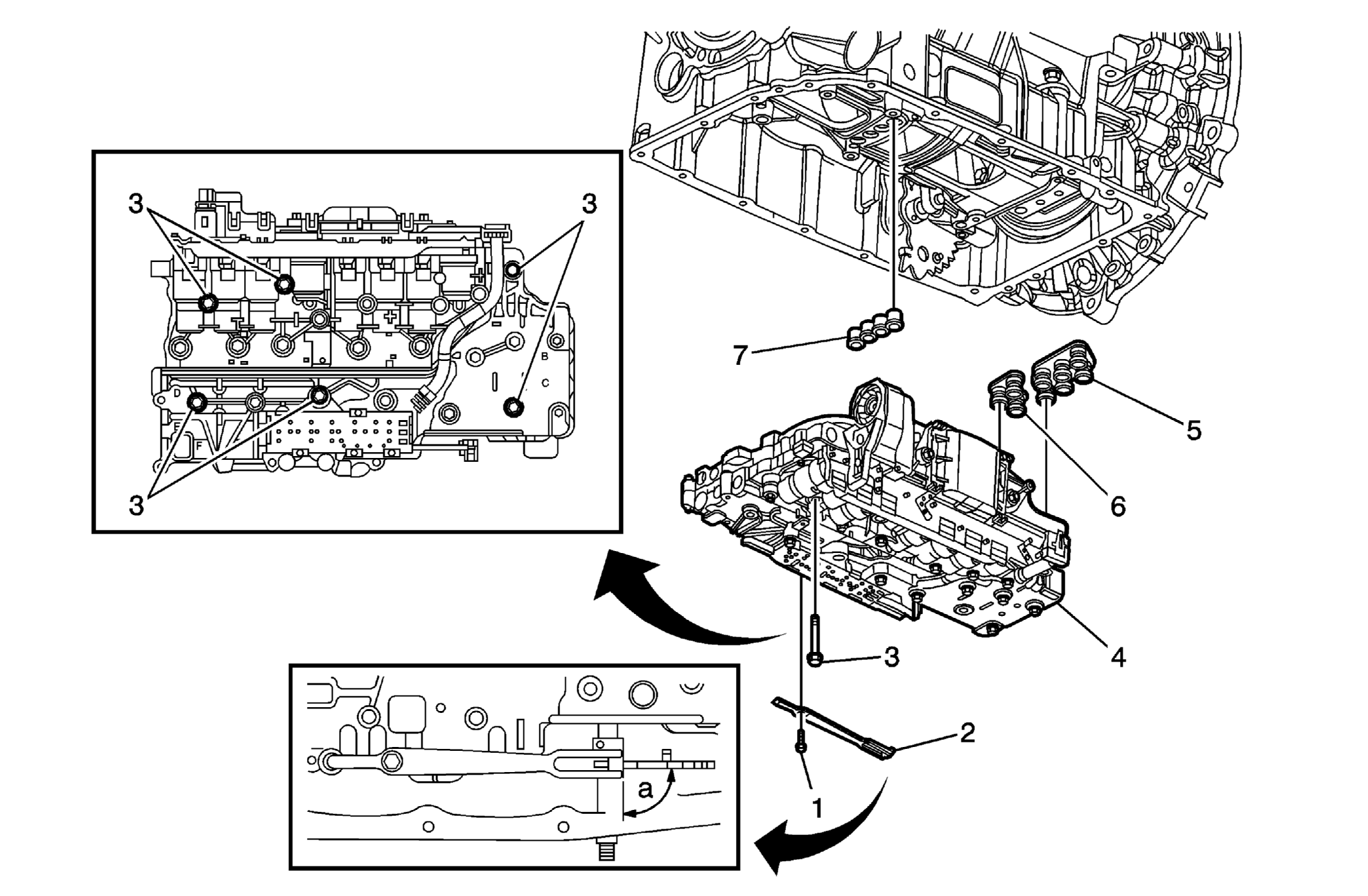 Courtesy of GENERAL MOTORS CORP.
 Control Valve Lower Body and Upper Body Replacement
| Callout |
Component Name |
|
Preliminary Procedures
- Raise and support the vehicle. Refer to Lifting and Jacking the Vehicle
.
- Remove the transmission fluid pan, gasket and filter. Refer to Automatic Transmission Fluid, Fluid Pan and/or Filter Replacement .
- Remove the electrical connector sleeve. Refer to Automatic Transmission Electrical Connector Passage Sleeve Replacement .
|
| 1 |
Manual Shaft Detent Assembly Bolt (Qty: 1)
Tighten:
12 N.m (106 lb in)
|
| 2 |
Manual Shaft Detent Assembly
Tip:
Ensure the manual shaft detent assembly roller is centered over the manual shaft detent lever assembly. Failure to center the roller may cause hard or no shift lever operation. |
| 3 |
Control Valve Assembly Bolt (Qty: 6) Procedure
- Do not remove all the bolts in the control valve body assembly. Remove only the bolts indicated.
- Tighten the bolts in the proper order. Refer to Control Valve Body Assembly Installation
in Unit Repair manual.
Tighten:
8 N.m (71 lb in)
|
| 4 |
Control Valve Assembly
Procedure:
Align the manual shift shaft position switch activator slide with the detent lever guide pin during control valve body installation.
Tip:
- For control valve body disassembly, refer to Control Valve Body Assembly Disassemble
in the Unit Repair manual.
- For control valve body cleaning and inspection, refer to Control Valve Lower Body Assembly Cleaning and Inspection
and Control Valve Upper Body Assembly Cleaning and Inspection
in the Unit Repair manual.
- For ball check valve locations, refer to Ball Check Valve Locations
in the Unit Repair manual.
- For control valve body assembly, refer to Control Valve Body Assembly Assemble
in the Unit Repair manual.
|
| 5 |
Fluid Pump Seal Assembly
Tip:
Do not reuse the seal assembly. |
| 6 |
Fluid Pump Seal Assembly
Tip:
Do not reuse the seal assembly. |
| 7 |
Center Support Fluid Passage Seal Assembly
Tip:
- Do not reuse the seal assembly.
- It is recommended that transmission adaptive pressure (TAP) information be reset. Transmission performance may be affected as new TAP values are learned. Reset the TAP values. Refer to Service Fast Learn Adapts .
|