Test M: Cruise Control Indicator Inoperative
- If cruise control diagnostic system check has been performed, go to next step. If cruise control diagnostic system check has not been performed, perform CRUISE CONTROL DIAGNOSTIC SYSTEM CHECK
under SELF-DIAGNOSTIC SYSTEM.
- Connect scan tool to Data Link Connector (DLC). DLC is located below left side of instrument panel, near steering column. Start engine and test drive vehicle at 25 MPH or more. Engage cruise control. Using scan tool, observe cruise requested parameter in Powertrain Control Module (PCM) data list. If scan tool displays YES, go to next step. If scan tool does not display YES, go to step 4
.
- Cycle ignition switch from OFF to RUN position. Observe CRUISE indicator during bulb check. If CRUISE indicator does not illuminate during bulb check, go to step 9
. If CRUISE indicator illuminates during bulb check, inspect for intermittents. See TROUBLE SHOOTING
.
- Turn ignition switch to OFF position. Disconnect Cruise Control Module (CCM) 10-pin harness connector. CCM is located in center of firewall. Connect a 3-amp fused jumper wire between ground and CCM harness connector terminal "J" (Light Blue/Black wire). See Fig 1
. Test drive vehicle at 25 MPH or more. Using scan tool, observe cruise requested parameter in PCM data list. If scan tool does not display YES, go to next step. If scan tool displays YES, go to step 7
.
- Inspect Light Blue/Black wire for an open, high resistance or short to voltage between CCM harness connector terminal "J" and PCM harness connector C2 terminal No. 24. See Fig 1
. If problem does not exist, go to next step. If problem exists, repair Light Blue/Black wire as necessary. After repair, go to step 11
.
- Inspect PCM harness connector for poor connections. If problem does not exist, go to step 8
. If problem exists, repair PCM harness connector as necessary. After repair, go to step 11
.
- Inspect CCM harness connector for poor connections. If problem does not exist, go to step 10
. If problem exists, repair CCM harness connector as necessary. After repair, go to step 11
.
- Replace PCM. Program PCM. See POWERTRAIN CONTROL MODULE
under PROGRAMMING. After repair, go to step 11
.
- Replace Instrument Panel Cluster (IPC). After repair, go to step 11
.
- Replace CCM, then go to next step.
- Operate system to verify repair. If system is not operating correctly, repeat test beginning at step 2
.
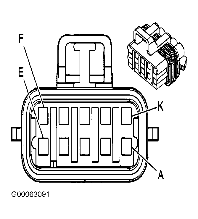 Courtesy of GENERAL MOTORS CORP.