Test AJ: Turn Signal Lights/Indicators Always On Or Flashing
- If lighting systems diagnostic system check has been performed, go to next step. If lighting systems diagnostic system check has not been performed, perform LIGHTING SYSTEMS DIAGNOSTIC SYSTEM CHECK
under SELF-DIAGNOSTIC SYSTEM.
- Turn ignition switch to RUN position. Place turn signal lever in neutral position. If turn signal lights/indicators remain illuminated, go to next step. If turn signal lights/indicators do not remain illuminated, inspect for intermittents. See TROUBLE SHOOTING
.
- If more than turn signal indicators remain illuminated, go to next step. If only turn signal indicators remain illuminated, go to step 10
.
- If turn signal lights flash, go to next step. If turn signal lights do not flash, go to step 6
.
- Disconnect hazard switch 10-pin harness connector. Connect a test light between ground and hazard switch harness connector terminal "B" (Light Green wire, left turn) or "D" (Dark Green wire, right turn). See Fig 1
. If test light illuminates, go to step 7
. If test light does not illuminate, go to step 9
.
- Turn ignition switch to OFF position. Disconnect hazard switch 10-pin harness connector. Turn ignition switch to RUN position. Connect a test light between ground and hazard switch harness connector terminal "K" (Light Blue wire, left turn) or "H" (Dark Blue wire, right turn). See Fig 1
. If test light does not illuminate, go to step 9
. If test light illuminates, go to step 11
.
- Inspect Light Green wire or Dark Green wire for a short to voltage between hazard switch harness connector and turn signal switch. If problem does not exist, go to next step. If problem exists, repair Light Green wire or Dark Green wire as necessary. After repair, go to step 15
.
- Inspect turn signal switch harness connector for poor connections. If problem does not exist, go to step 12
. If problem exists, repair turn signal switch harness connector as necessary. After repair, go to step 15
.
- Inspect hazard switch harness connector for poor connections. If problem does not exist, go to step 13
. If problem exists, repair hazard switch harness connector as necessary. After repair, go to step 15
.
- Inspect Instrument Panel Cluster (IPC) harness connector for poor connections. If problem does not exist, go to step 14
. If problem exists, repair IPC harness connector as necessary. After repair, go to step 15
.
- Repair short to voltage in Light Blue wire or Dark Blue wire between hazard switch and suspect turn signal light. After repair, go to step 15
.
- Replace turn signal switch. After repair, go to step 15
.
- Replace hazard switch. After repair, go to step 15
.
- Replace IPC, then go to next step.
- Operate system to verify repair. If system is not operating correctly, repeat test beginning at step 2
.
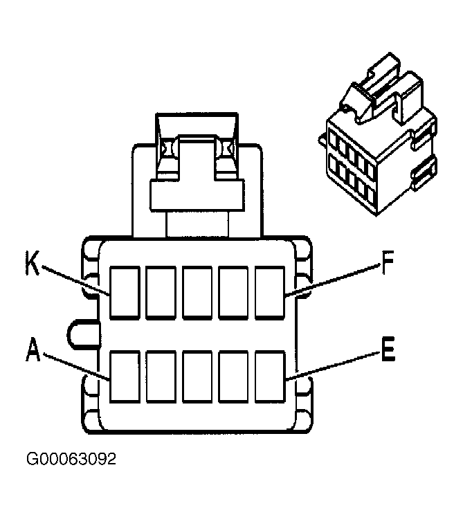 Courtesy of GENERAL MOTORS CORP.