Installation (Upper)
- Align the IP upper trim pad to the IP and connect the harness connectors. Slide the IP upper trim pad forward in order to engage the front of the IP trim pad to the IP carrier. See Fig 3. Align the rear edge of IP upper trim pad with IP cluster bezel and snap retainers into upper pad. Replace all instrument panel air outlet vents. See INSTRUMENT PANEL AIR OUTLET VENT . Go to next step.
- Install the 4 screws into the IP air outlet vent openings. See Fig 2. Tighten the trim panel screws to 18 INCH lbs. (2 N.m). Install the 3 screws into the defroster grille opening on the IP upper pad. Tighten the trim panel screws to 18 INCH lbs. (2 N.m). Go to next step.
- Partially install the defroster grille. Figure. Reconnect the sunload sensor harness connector. Insert the forward edge of the defroster grille to the IP. Align the defroster grille with the IP opening. Press down along the rear edge of the defroster grille to engage the retainer clips. See Figure. Align the air outlet vents to the IP opening. See Figure. Push the air outlet vents into the opening until the retainers are engaged. See Figure. Check for proper operation and movement. Go to next step.
- Position the lower the end of the windshield pillar garnish molding behind instrument panel cover. Align the clips to the holes in the windshield pillar. See Fig 1. Push in on the windshield pillar garnish molding to engage the retainer clips.
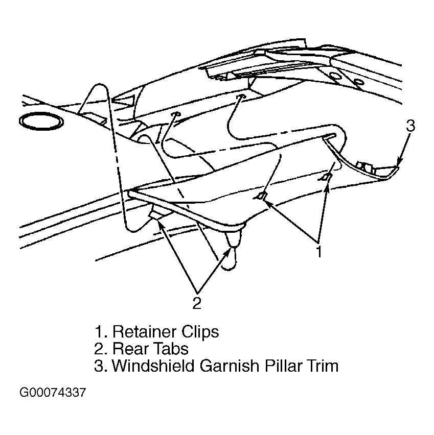 Courtesy of GENERAL MOTORS CORP.
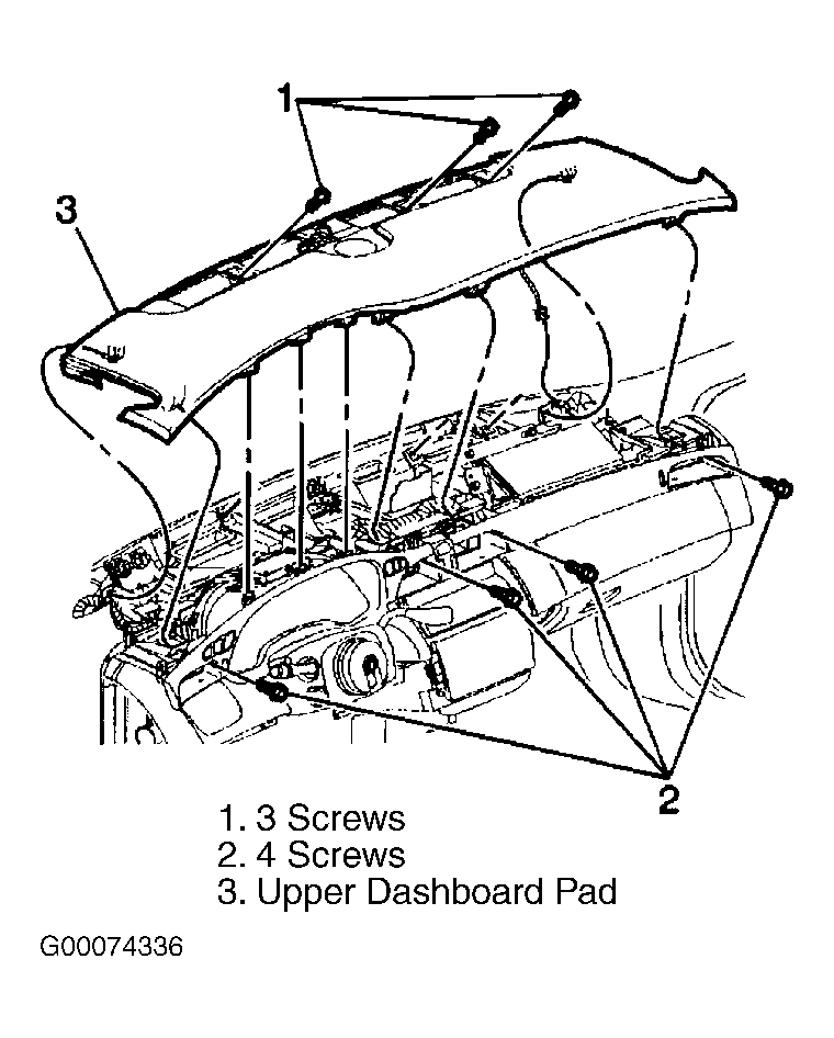 Courtesy of GENERAL MOTORS CORP.
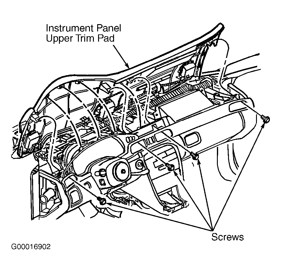 Courtesy of GENERAL MOTORS CORP.