Fuel Pump Electrical Circuit Diagnosis
- If powertrain diagnostic system check has already been performed, go to next step. If powertrain diagnostic system check has not been performed, go to POWERTRAIN DIAGNOSTIC SYSTEM CHECK under DIAGNOSTIC SYSTEM CHECKS in appropriate SELF-DIAGNOSTICS article.
- Turn ignition on. Using scan tool, command fuel pump relay on and off. If fuel pump relay turns on and off as commanded, no problem is indicated at this time. Fault may be intermittent. If fuel pump relay does not turn on and off as commanded, go to next step.
- Using scan tool, command fuel pump relay on and off. Listen for fuel pump relay operating click noise. Fuel pump relay is located in rear fuse block. Rear fuse block is located underneath driver's side rear seat. If fuel pump relay operating noise is heard as relay is commanded on and off, go to step 9. If fuel pump relay operating noise is not heard as relay is commanded on and off, go to next step.
- Turn ignition off. Remove fuel pump relay. Turn ignition on. Using a test light connected to ground, probe fuel pump relay control circuit (Dark Green/White wire) at fuel pump relay connector in rear fuse block. See WIRING DIAGRAMS article. Using scan tool, command fuel pump relay on and off. If test light turns on and off as commanded, disconnect test light and go to next step. If test light does not turn on and off as commanded, go to step 6.
- Turn ignition off. Connect a test light between fuel pump relay control circuit (Dark Green/White wire) and fuel pump relay ground circuit (Black wire) at fuel pump relay connector in rear fuse block. Turn ignition on. Using scan tool, command fuel pump relay on and off. If test light turns on and off as commanded, go to step 21. If test light does not turn on and off as commanded, go to step 24.
- If test light is always on, go to next step. If test light is always off, go to step 8.
- Turn ignition off. Disconnect PCM connectors. PCM is located in engine compartment, inside air filter housing. Using a test light connected to ground, probe terminal No. 3 (Dark Green/White wire) at PCM C2 harness connector. See Fig 1. If test light illuminates, repair short to voltage in Dark Green/White wire between PCM and fuel pump relay connector. After repairs, go to step 29. If test light does not illuminate, go to step 28.
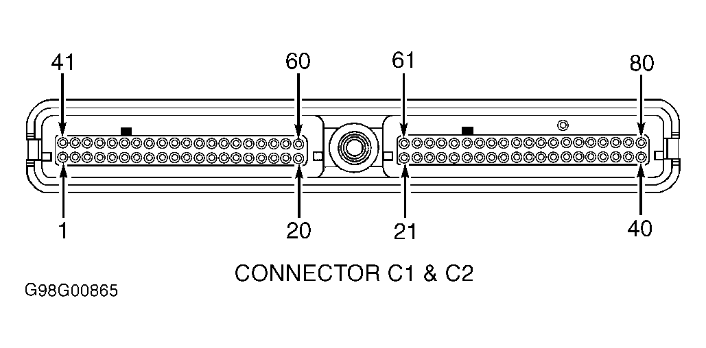 Courtesy of GENERAL MOTORS CORP.
- Turn ignition off. Disconnect PCM connectors. PCM is located in engine compartment, inside air filter housing. On 3.5L, check for an open or short to ground in fuel pump relay control circuit (Dark Green/White wire) between fuel pump relay connector in rear fuse block and terminal No. 3 at PCM C2 harness connector. See Fig 1. On 4.0L, check for an open or short to ground in fuel pump relay control circuit (Dark Green/White wire) between fuel pump relay connector in rear fuse block and terminal No. 70 at PCM C1 harness connector. See Fig 1. On all models, if Dark Green/White wire is open or shorted to ground, repair wiring as necessary. After repairs, go to step 29. If Dark Green/White wire is not open or shorted to ground, go to step 22.
- Turn ignition on. If fuel pump runs continuously, go to next step. If fuel pump does not run continuously, go to step 11.
- Turn ignition off. Remove fuel pump relay. If fuel pump still runs continuously, go to step 23. If fuel pump does not run continuously, go to step 27.
- Inspect fuse No. 1 (F/PMP) in rear fuse block. Rear fuse block is located underneath driver's side rear seat. If fuse is blown, go to next step. If fuse is okay, go to step 14.
- Disconnect fuel pump harness in-line connector located near right side of fuel tank. Using a test light connected to positive battery voltage, probe Gray wire at fuel pump harness in-line connector. If test light illuminates, repair short to ground in Gray wire. After repairs, go to step 29. If test light does not illuminate, go to next step.
- Check for damaged or shorted fuel pump wiring harness. Fuel pump can be accessed through an inspection panel in trunk. To inspect complete wiring harness, if may be necessary to lower fuel tank. Repair wiring harness as necessary and replace fuse. After repairs, go to step 29. If wiring harness is okay, go to step 20.
- Turn ignition off. Remove fuel pump relay. Turn ignition on. Using a test light connected to ground, probe voltage supply circuit at fuel pump relay connector in rear fuse block. See WIRING DIAGRAMS article. If test light illuminates, go to next step. If test light does not illuminate, go to step 25.
- Connect a 20-amp fused jumper wire between voltage supply circuit and fuel pump supply circuit (Gray wire) at fuel pump relay connector in rear fuse block. If fuel pump operates, go to step 21. If fuel pump does not operate, go to next step.
- Disconnect fuel pump harness in-line connector located near right side of fuel tank. Check for an open or high resistance in Gray wire between fuel pump relay connector in rear fuse block and fuel pump harness in-line connector. Repair wiring as necessary. After repairs, go to step 29. If wiring is okay, go to next step.
- Check for an open or high resistance is fuel pump ground circuit (Black wire) between fuel pump and ground connection. See WIRING DIAGRAMS article. Repair wiring as necessary. After repairs, go to step 29. If wiring is okay, go to next step.
- Check for poor connections at fuel pump harness in-line connector located near right side of fuel tank. Repair connector as necessary. After repairs, go to step 29. If connector is okay, go to next step.
- Check for damaged or open fuel pump wiring harness. Fuel pump can be accessed through an inspection panel in trunk. To inspect complete wiring harness, if may be necessary to lower fuel tank. Repair wiring harness as necessary. After repairs, go to step 29. If wiring harness is okay, go to step 26.
- Reconnect all components. Install a new No. 1 (F/PMP) fuse. Using scan tool, command fuel pump on. Recheck fuse No. 1 (F/PMP) in rear fuse block. If fuse is blown, go to step 26. If fuse is okay, no problem is indicated at this time. Fault may be intermittent.
- Check fuel pump relay connector for poor connections. Repair connector as necessary. After repairs, go to step 29. If connector is okay, go to step 27.
- Check PCM connectors for poor connections. PCM is located in engine compartment, inside air filter housing. Repair connectors as necessary. After repairs, go to step 29. If connectors are okay, go to step 28.
- Repair short to voltage fuel pump supply circuit (Gray wire) between fuel pump and fuel pump relay. After repairs, go to step 29.
- Repair open in fuel pump relay ground circuit. See WIRING DIAGRAMS article. After repairs, go to step 29.
- Repair open in voltage supply circuit to fuel pump relay. See WIRING DIAGRAMS article. After repairs, go to step 29.
- Check fuel pump connector for poor connections. Repair connector as necessary. If connector is okay, replace fuel pump. After repairs, go to step 29. Replace fuse No. 1 (F/PMP), if necessary.
- Replace fuel pump relay. After repairs, go to step 29.
- Replace PCM. Program replacement PCM. See PROGRAMMING in appropriate SELF-DIAGNOSTICS article. After repairs, go to next step.
- Turn ignition off. Reconnect all disconnected connectors. Turn ignition on. Using scan tool, clear DTCs. Turn ignition off for 30 seconds. Start engine. If engine starts and continues to idle, system is okay. If engine does not start or continue to idle, go to step 2.