Test C: Engine Coolant Temperature Gauge Inoperative/Inaccurate
- If instrument panel cluster diagnostic system check has been performed, go to next step. If instrument panel cluster diagnostic system check has not been performed, go to INSTRUMENT PANEL CLUSTER DIAGNOSTIC SYSTEM CHECK
under SELF-DIAGNOSTIC SYSTEM.
- Connect scan tool to Data Link Connector (DLC). DLC is located under left side of instrument panel. Turn ignition switch to RUN position. Using scan tool, observe COOLANT TEMP parameter in Instrument Panel Cluster (IPC) data list. If parameter matches temperature gauge display, go to next step. If parameter does not match temperature gauge display, go to step 4
.
- Using scan tool, observe ECT SENSOR parameter in Powertrain Control Module (PCM) data list. If COOLANT TEMP parameter does not match ECT SENSOR parameter, go to next step. If COOLANT TEMP parameter matches ECT SENSOR parameter, repair overheating concern.
- Turn ignition switch to OFF position. Disconnect in-line White 20-pin harness connector C105. In-line harness connector is located at left front of engine compartment, behind battery. Turn ignition switch to RUN position. Coolant temperature gauge should register 100°F (37°C). If gauge displays specified value, go to next step. If gauge does not display specified value, go to step 7
.
- Turn ignition switch to OFF position. Connect Signal Generator and Instrument Panel Tester (J 33431-C) between ground and Engine Coolant Temperature (ECT) sensor signal circuit (Blue wire). See WIRING DIAGRAMS
. Set resistance on signal generator to 44 ohms. Turn ignition switch to RUN position. Coolant temperature gauge should register 280°F (138°C). If gauge does not display specified value, go to next step. If gauge displays specified value, go to step 8
.
- Check for open, high resistance or short to voltage in Blue wire between ECT sensor harness connector terminal No. 1 and IPC harness connector C1 terminal No. 21. See Figure
. If problem is found, repair as necessary and go to step 14
. If no problem is found, go to step 11
.
- Check for short to ground in Blue wire between ECT sensor harness connector terminal No. 1 and IPC harness connector C1 terminal No. 21. See Figure
. If problem is found, repair as necessary and go to step 14
. If no problem is found, go to step 11
.
- Check for open, high resistance, short to ground or short to voltage in Blue wire between ECT harness connector terminal No. 1 and in-line harness connector C105 terminal No. 15. See Fig 1
. If no problem is found, go to next step. If problem is found, repair as necessary and go to step 14
.
- Check for poor connection or high resistance in ECT sensor case ground. If no problem is found, go to next step. If problem is found, repair as necessary and go to step 14
.
- Check for poor, loose or corroded terminal in ECT sensor harness connector. If problem is found, repair as necessary and go to step 14
. If no problem is found, go to step 12
.
- Check for poor, loose or corroded terminal in IPC harness connector. If problem is found, repair as necessary and go to step 14
. If no problem is found, go to step 13
.
- Replace ECT sensor. After repairs are made, go to step 14
.
- Replace IPC. See INSTRUMENT PANEL CLUSTER
under REMOVAL & INSTALLATION. After repairs are made, go to next step.
- Using scan tool clear any DTCs. Operate system to verify repair. If system operates normally, testing is complete. If system does not operate normally, go to step 2
.
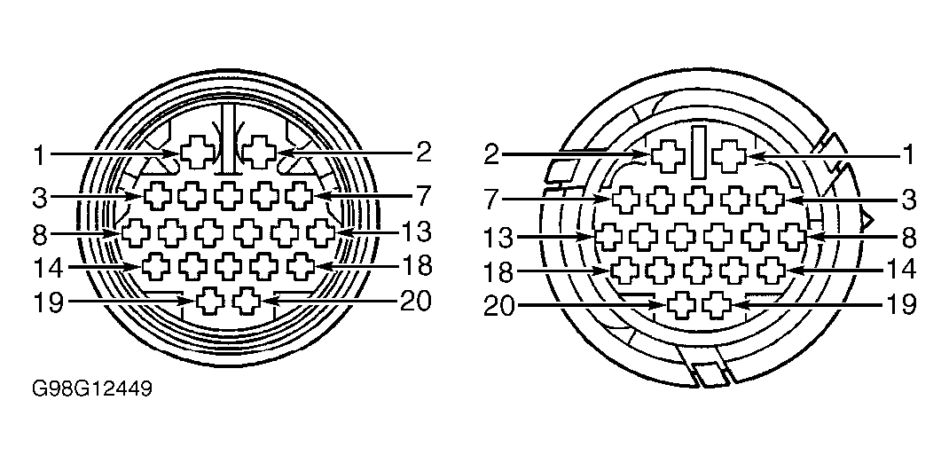 Courtesy of GENERAL MOTORS CORP.