Test Aa: Turn Signal Lamps And/Or Indicators Inoperative
- If lighting system diagnostic systems check has been performed, go to next step. If lighting system diagnostic systems check has not been performed, go to LIGHTING SYSTEM DIAGNOSTIC SYSTEMS CHECK under SELF-DIAGNOSTIC SYSTEM in BODY CONTROL MODES - CATERA article.
- Turn ignition switch to RUN position. Move turn signal switch from left to right positions, while observing turn signal lights and indicators. If turn signal lights and indicators do not operate normally, go to next step. If turn signal lights and indicators operate normally, concern may be intermittent. See PROBLEM DIAGNOSIS
under INTERMITTENTS.
- If all turn signals and indicators are not inoperative, go to next step. If all turn signals and indicators are inoperative, go to step 6
.
- If front or rear left hand turn signal is operative, go to next step. If front or rear left hand turn signal is inoperative, go to step 19
.
- If front or rear right hand turn signal is inoperative, go to step 16
. If front or rear right hand turn signals are operative, go to step 22
.
- Check instrument panel fuse block FLASHER fuse (10-amp). If fuse is okay, go to next step. If fuse is blown, go to step 12
.
- Check instrument panel fuse block HZD fuse (20-amp). If fuse is okay, go to next step. If fuse is blown, go to step 27
.
- Press hazard warning switch to on. If hazard lights do not operate normally, go to next step. If hazard lights operate normally, go to step 12
.
- Press hazard switch to OFF position. Turn ignition switch to RUN position. Remove turn signal light flasher from instrument panel convenience center. Convenience center is located under left side of instrument panel. See Fig 1
. Using test light connected to ground, probe turn signal light flasher module socket cavity No. 6 (Blue wire) supply voltage circuit. See Fig 2
. If test light does not illuminate, go to next step. If test light illuminates, go to step 11
.
- Disconnect hazard switch 9-pin harness connector. Hazard switch is located in instrument panel, to left of radio. Using test light connected to ground, probe hazard switch harness connector terminal No. 9 (Brown wire). If test light illuminates, go to step 13
. If test light does not illuminate, go to step 28
.
- Connect test light between turn signal light flasher module socket cavities No. 4 (Black wire) and No. 6 (Red wire). If test light illuminates, go to step 33
. If test light does not illuminate, go to step 25
.
- Press hazard switch to OFF position. Turn ignition switch to RUN position. Remove turn signal light flasher from instrument panel convenience center. Convenience center is located under left side of instrument panel. See Fig 1
. Using test light connected to ground, probe turn signal light flasher module socket cavity No. 6 (Blue wire) supply voltage circuit. See Fig 2
. If test light illuminates, go to step 14
. If test light does not illuminates, go to step 15
.
- Check for open or high resistance in turn signal/hazard flasher supply voltage circuit (Blue wire) between hazard warning switch harness connector terminal No. 3 and turn signal/hazard flasher module harness connector No. 6. If problem is found, repair as necessary and go to step 34
. If no problem is found, go to step 32
.
- Check for open or a high resistance in turn signal flasher signal circuit (Black/White wire) between turn signal/hazard flasher module harness connector No. 8 and both hazard warning switch harness connector terminal No. 3 or turn signal switch harness connector No. 4. If problem is found, repair as necessary and go to step 34
. If no problem is found, go to step 30
.
- Check for open or high resistance in hazard warning switch ignition supply voltage circuit (Brown wire) between instrument panel fuse block FLASHER fuse (10-amp) and hazard warning switch harness connector terminal No. 9. See Fig 3
. If problem is found, repair as necessary and go to step 34
. If no problem is found, go to step 32
.
- Observe right hand turn signals. If both front and rear turn signals are inoperative, go to next step. If only one turn signal is inoperative, go to step 18
.
- Check for open or high resistance in right hand turn signal switch turn light supply voltage circuit (Black/Green wire) between turn signal switch harness connector terminal No. 8 and Instrument Panel Cluster (IPC) harness connector C1 terminal No. 18. If problem is found, repair as necessary and go to step 34
. If no problem is found, go to step 30
.
- Check for open or high resistance in ground circuit and supply voltage circuit of inoperative lamp. See EXTERIOR LIGHTS article. If problem is found, repair as necessary and go to step 34
. If no problem is found, go to step 31
.
- Observe left hand turn signals. If both front and rear turn signals are inoperative, go to next step. If only one turn signal is inoperative, go to step 21
.
- Check for open or high resistance in left hand turn signal switch turn light supply voltage circuit (Black/White wire) between turn signal switch harness connector terminal No. 9 and IPC harness connector C1 terminal No. 6. If problem is found, repair as necessary and go to step 34
. If no problem is found, go to step 30
.
- Check for open or high resistance in ground circuit and supply voltage circuit of inoperative lamp. See EXTERIOR LIGHTS article. If problem is found, repair as necessary and go to step 34
. If no problem is found, go to step 31
.
- If turn signal indicators are inoperative, determine if one indicator or both indicators are inoperative. If only one turn signal indicator is inoperative, go to next step. If both turn signal indicators are inoperative, go to step 29
.
- Check inoperative turn signal indicator bulb, and replace as necessary. If bulb was defective, go to next step. If bulb was not defective, go to step 34
.
- Check for open or high resistance in inoperative turn signal indicator circuit. See WIRING DIAGRAMS
. See EXTERIOR LIGHTS article. If problem is found, repair as necessary and go to step 34
. If no problem is found, go to step 29
.
- Repair open or high resistance in turn signal light flasher module ground circuit (Black wire) between ground and turn signal light flasher module harness connector terminal No. 4. After repairs are made, go to step 34
.
- Repair short to ground in hazard warning switch ignition supply voltage circuit (Brown wire) between instrument panel fuse block FLASHER fuse and hazard warning switch harness connector terminal No. 9. Repair short to ground in turn signal lamp flasher supply voltage circuit (Blue wire) between hazard warning switch harness connector terminal No. 3 and turn signal/hazard flasher module harness connector terminal No. 6. See Fig 2
and Fig 3
. After repairs are made, go to step 34
.
- Repair short to ground in hazard warning switch battery supply voltage circuit (Red wire) between instrument panel fuse block HZD fuse and hazard warning switch harness connector terminal No. 6. After repairs are made, go to step 34
.
- Repair open or high resistance in hazard warning switch supply voltage circuit (Brown wire) between instrument panel fuse block FLASHER fuse and hazard warning switch harness connector terminal No. 9. See WIRING DIAGRAMS
. After repairs are made, go to step 34
.
- Replace IPC. See INSTRUMENT PANEL CLUSTER
under REMOVAL & INSTALLATION. After repairs are made, go to step 34
.
- Replace turn signal switch. See STEERING COLUMN SWITCHES - CATERA article. After repairs are made, go to step 34
.
- Replace inoperative park/turn signal lamp. Replace inoperative rear turn signal bulb. After repairs are made, go to step 34
.
- Replace hazard warning switch. See HAZARD WARNING SWITCH
under REMOVAL & INSTALLATION. After repairs are made, go to step 34
.
- Check for poor, loose or corroded terminals in all turn signal system harness connectors. If problem is found, repair as necessary and go to next step. If no problem is found, replace turn signal/hazard flasher module. After repairs are made, go to next step.
- Connect all harness connectors and components that were previously disconnected. Verify that turn signal lamps and indicators operate properly. If system operates normally, testing is complete. If system does not operate normally, go to step 2
.
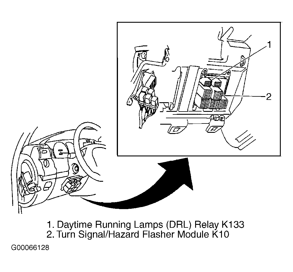 Courtesy of GENERAL MOTORS CORP.
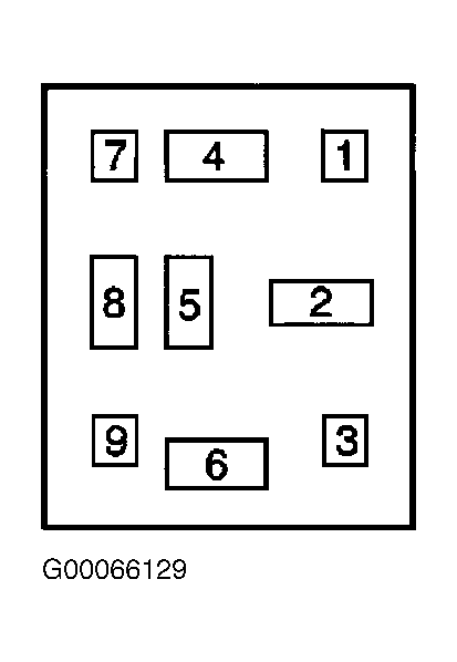 Courtesy of GENERAL MOTORS CORP.
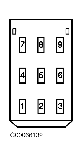 Courtesy of GENERAL MOTORS CORP.