Test A: Brake Pad Wear Indicator Always On
- Ensure front brake linings are okay. See appropriate article in BRAKES. Go to next step.
- Disconnect right brake pad wear sensor harness connector. Turn ignition on. Measure voltage between right brake pad wear sensor harness connector terminals No. 2 (Gray/Red wire) and No. 3 (Black wire). If voltage is about 12 volts, go to next step. If voltage is not about 12 volts, go to step 4
.
- Measure resistance between right brake pad wear sensor terminals No. 2 and 3. If resistance is less than .5 ohm, go to step 5
. If resistance is .5 ohm or more, go to step 6
.
- Turn ignition off. Measure resistance between ground and right brake pad wear sensor harness connector terminal No. 3 (Black wire). If resistance is less than .5 ohm, go to step 7
. If resistance is .5 ohm or more, go to step 8
.
- Inspect gauge cluster harness connector for poor connections. Repair connector as necessary and go to step 9
. If connector is okay, go to step 10
.
- Replace right brake pad wear sensor. Go to step 9
.
- Disconnect left brake pad wear sensor harness connector. Measure resistance between left brake pad wear sensor connector (sensor side) terminals No. 2 (Yellow/Red wire) and No. 3 (Gray/Red wire). If resistance is less than .5 ohm, go to step 11
. If resistance is .5 ohm or more, go to step 12
.
- Repair open in Black wire between right brake pad wear sensor harness connector terminal No. 3 and ground. See WIRING DIAGRAMS
. Go to next step.
- Reconnect all harness connectors and reinstall all components. Turn ignition on. Disconnect one brake pad wear sensor harness connector. If brake pad wear indicator turns on, system is okay. If brake pad wear indicator does not turn on, go to step 2
.
- Replace gauge cluster. See INSTRUMENT CLUSTER GAUGES
under REMOVAL & INSTALLATION. Go to step 9
.
- Turn ignition on. Measure voltage between ground and left brake pad wear sensor harness connector terminal No. 2 (Yellow/Red wire). If voltage is about 12 volts, go to step 13
. If voltage is not about 12 volts, go to step 14
.
- Replace left brake pad wear sensor. Go to step 9
.
- Check for open in Gray/Red wire between left brake pad wear sensor harness connector terminal No. 3 and right brake pad wear sensor harness connector terminal No. 2. Repair circuit as necessary and go to step 9
. If circuit is okay, go to step 15
.
- Check for open in Yellow/Red wire between left brake pad wear sensor harness connector terminal No. 2 and gauge cluster harness connector terminal No. 2. See Fig 1
. Repair circuit as necessary and go to step 9
. If circuit is okay, go to next step.
- Fault is intermittent. Check related harness connectors for poor connections. Check for faulty wiring. Repair as necessary and go to step 9
.
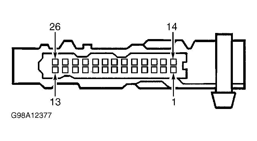 Courtesy of GENERAL MOTORS CORP.