All Gauges Inoperative
- Check IGN 1 fuse located in rear junction block. See COMPONENT LOCATIONS
. If fuse is blown, go to step 3). If fuse is okay, go to next step.
- Check I/P fuse located in underhood junction block. See COMPONENT LOCATIONS
. If fuse is blown, go to step 4). If fuse is okay, go to step 5).
- Repair open or short to ground in Pink wire between IPC and rear junction block. Replace fuse and recheck system operation.
- Repair open or short to ground in Orange wire between IPC and underhood junction block. Replace fuse and recheck system operation.
- Turn ignition switch to OFF position. Disconnect IPC connector C2. See INSTRUMENT PANEL CLUSTER
under REMOVAL & INSTALLATION. Use DVOM to measure voltage between ground and IPC connector C2 terminal A1 (Orange wire). See Fig 1
. If reading is 10.5-15 volts, go to next step. If reading is not 10.5-15 volts, go to step 4).
- Turn ignition switch to ON position. Use DVOM and measure voltage between ground and IPC connector C2 terminal A3 (Pink wire). If reading is 10.5-15 volts, go to next step. If reading is not 10.5-15 volts, go to step 3).
- Turn ignition switch to ON position. Use DVOM and measure voltage between IPC connector C2 terminals A1 (Orange wire) and B6 (Black/White wire). If reading is 10.5-15 volts, go to step 9). If reading is not 10.5-15 volts, go to next step.
- Repair open in Black/White wire between IPC and ground. Recheck system operation.
- Turn ignition switch to ON position. Use DVOM to measure voltage between IPC connector C2 terminals A1 (Orange wire) and B7 (Black wire). If reading is 10.5-15 volts, go to step 11). If reading is not 10.5-15 volts, go to next step.
- Repair open in Black wire between IPC and ground. Recheck system operation.
- Replace IPC. See INSTRUMENT PANEL CLUSTER
under REMOVAL & INSTALLATION. Recheck system operation.
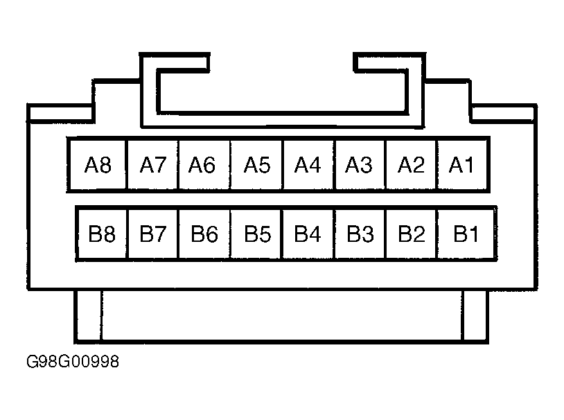 Courtesy of GENERAL MOTORS CORP.