Multiple Data Communication Codes
- Ensure ALDL cover is properly seated to ALDL connector. If it is, go to step 3). If it is not, clear all codes, install ALDL cover properly and test drive vehicle for more than 10 miles. Enter self-diagnostics and recheck for trouble codes. See ENTERING SELF-DIAGNOSTICS under SELF-DIAGNOSTICS.
- ALDL cover contains a serial data line jumper connection. When ALDL cover is in place, this jumper connects ALDL terminals "M" and "L" to complete the serial data line communication link between all computer systems. See Fig 1.
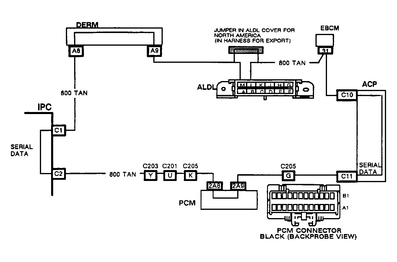 Courtesy of GENERAL MOTORS CORP.
- Ensure ALDL cover is properly positioned. Enter self-diagnostics and record all trouble codes. See ENTERING SELF-DIAGNOSTICS under SELF-DIAGNOSTICS. If both codes I033 and I037 are set, repair open in Tan wire between DERM to IPC or between ACP to PCM. Diagnostic Energy Reserve Module (DERM) is located directly above gas pedal and to right of cruise control vacuum brake switch/stoplight switch assembly. DERM has Yellow connector and wiring harness. A/C Programmer (ACP) is located left of PCM, behind glove box. If both codes I034 and I037 are set, repair open in Tan wire between IPC and PCM or between ACP and DERM. See Fig 1. See appropriate chassis wiring diagram in WIRING DIAGRAMS
in the ENGINE PERFORMANCE section.
- If both codes I034 and E052 are set, PCM has lost power. Diagnose as per PCM code E052. See BASIC TESTING
article in the ENGINE PERFORMANCE Section. If both codes I034 and E047 are set, IPC has lost communications with PCM. Diagnose as per IPC code I034. If both codes I037 and A037 are set, IPC has lost communications with ACP. Diagnose as per IPC code I037.
- If codes I052, A037 and E047 are all set, there is serial data line communication link break down. Diagnose as per IPC code I052. If codes I033, I034 and I037 are all set, and these are current ("C") codes, go to next step. If these are history ("H") codes, check the following and repair as needed.
- Check for poor connections at IPC terminals C1 and C2. See Figure.
- Check for intermittent short to ground or short to battery voltage anywhere in Tan wire circuit. See Fig 1.
- Check for intermittent open in Tan wire circuit between IPC and DERM, and between IPC and PCM.
- Check each computer component along Tan wire circuit to be holding serial data line at a constant voltage.
- Disconnect PCM connector C2. See Fig 2. PCM is located on right kick panel. Remove ALDL cover. Using DVOM, measure voltage at ALDL terminal "M". If voltage does not fluctuate between 3 and 5 volts, go to step 11). If voltage fluctuates between 3 and 5 volts, disconnect ACP connector and reconnect PCM connector C2. ACP is located left of PCM. Using DVOM, measure voltage at ALDL terminal "M".
- If voltage is fluctuating between 3-5 volts, go to step 9). If voltage is not fluctuating between 3-5 volts, disconnect PCM connectors. Using jumper wire, connect PCM harness connector C2, terminals A8 and A9. See Fig 2.
 Courtesy of GENERAL MOTORS CORP.
- Using DVOM, measure voltage at ALDL terminal "M". If voltage is fluctuating between 3-5 volts, check PCM MEM-CAL for good connection into PCM, and check PCM connectors for good connections. If no connection problems exist, replace PCM. If voltage is not fluctuating between 3-5 volts at terminal "M", repair short in Tan wire circuit between ACP and PCM.
- If voltage is fluctuating between 3-5 volts, use jumper wire to connect ACP harness connector terminals C10 and C11. See Fig 3. Using DVOM, measure voltage at ALDL terminal "M". If voltage is fluctuating between 3-5 volts, check for faulty ACP connections. If ACP connections are good, replace ACP.
 Courtesy of GENERAL MOTORS CORP.
- If voltage does not fluctuate between 3 and 5 volts at ALDL terminal "M", disconnect Electronic Brake Control Module (EBCM) connector. EBCM is mounted to center of cross brace behind rear seat and is accessible from trunk. Using DVOM, measure voltage at ALDL terminal "M". If voltage fluctuates between 3 and 5 volts, replace EBCM. If voltage does not fluctuate between 3 and 5 volts, repair short in Tan wire between ACP and ALDL terminal "L".
- Ensure PCM connector and ALDL cover are still disconnected. Disconnect Yellow DERM connector. DERM is mounted vertically behind instrument panel to left of steering column and above gas pedal. Using DVOM, measure voltage at DERM harness connector terminal A8. See Fig 4. If voltage is not fluctuating between 3-5 volts, go to step 13). If voltage is fluctuating between 3-5 volts at DERM harness connector terminal A8, use jumper wire to connect DERM harness connector terminals A8 to A9. Measure voltage at ALDL terminal "M".
 Courtesy of GENERAL MOTORS CORP.
- If voltage fluctuates between 3 and 5 volts at ALDL terminal "M", check connections at DERM terminals. If connections are good, replace DERM. If voltage does not fluctuate between 3 and 5 volts at ALDL terminal "M", repair short in Tan wire circuit between DERM and ALDL terminal "M". See appropriate chassis wiring diagram in WIRING DIAGRAMS
in the ENGINE PERFORMANCE section.
- If voltage does not fluctuate between 3 and 5 volts at DERM harness connector terminal A8, turn ignition off. Disconnect IPC connectors. Leave DERM disconnected. Using DVOM, measure resistance to ground from IPC harness connector terminal C1. See Figure. If resistance is 2000 ohms or less, repair short in Tan wire circuit between DERM and IPC. See appropriate chassis wiring diagram in WIRING DIAGRAMS
in the ENGINE PERFORMANCE section.
- If resistance is more than 2000 ohms, connect jumper wire from DERM harness connector terminal A8 to ground. Measure resistance to ground from IPC harness connector terminal C1. If resistance is more than 2000 ohms, repair open in Tan wire circuit between IPC and DERM.
- If resistance is 2000 ohms or less, ensure PCM is still disconnected and measure resistance from ground to IPC harness connector terminal C2. If resistance is now more than 2000 ohms and terminal connections are good at IPC connectors, replace IPC. If resistance is 2000 ohms or less, repair short in Tan wire circuit between IPC and PCM. After all repairs are completed, clear all codes and verify correct operation.