IPC Dimming Problem
- IPC monitors parking light input circuit (Brown wire) from headlight switch to determine when headlight/parking lights are on. When lights are on, headlight switch converts dimming control output to pulse width modulation signal (PWM).
- This PWM signal is distributed to interior lighting units (i.e. radio, IPC, console, etc.). IPC "sees" parking lights "on" input (ID42) at IPC terminal D3. IPC then knows when to monitor dimming input (ID42) at IPC terminal C10 to control dimming of IPC and radio vacuum fluorescent (VF) displays. See Fig 1.
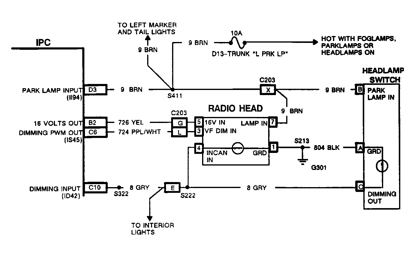 Courtesy of GENERAL MOTORS CORP.
- To test dimming, enter self-diagnostics and record all trouble codes. See ENTERING SELF-DIAGNOSTICS under SELF-DIAGNOSTICS. If code I022 is set, repair this code problem before proceeding. See TROUBLE CODES under SELF-DIAGNOSTICS. Exit self-diagnostics. Turn headlights on. Rotate dimmer switch while noting operation of backlighting for radio, IPC buttons, PRNDL indicator, etc., and all VF Green displays.
- If any or all bulb type lights fail to illuminate or dim, or lights stay on continuously, go to step 10). If all bulb type backlighting lights do illuminate, notice VF Green lighting. If radio VF dims correctly but IPC remains bright, replace IPC. If radio VF and IPC are bright and do not change with dimmer, problem is with IPC. Continue to next step. If IPC does dim, but radio does not, go to step 6). If radio does dim but IPC is blank, go to step 9).
- Enter diagnostics and select input parameter II94. Turn headlights on. If II94 reads HI, replace IPC. If II94 reads LO, repair open in Brown wire circuit between IPC and splice S411. S411 is located to the left side of rear seat bottom section, enclosed in a flat plastic harness cover. S411 is located inside this flat cover about 5 inches from bottom of cover.
- If IPC does dim, but radio does not and radio remains blank, replace radio control head. If radio remains full bright, enter self-diagnostics and select IPC OVERRIDE IS45 (VF Output). See ENTERING SELF-DIAGNOSTICS under SELF-DIAGNOSTICS. Locate radio control head connector C2 terminal 3 (Purple/White wire). This operation may require removal of radio control head from dash if vehicle is console equipped.
- Using DVOM, backprobe radio control head connector C2 terminal 3 (Purple/White wire) while moving value of IS45 from 00 to 99. At "99" value, IPC should be at full bright and DVOM should read about zero volts. At "00" value, IPC should be at maximum dim (black out) and DVOM should read about 5 volts. If voltage readings are not as described, repair open or short in Purple/White wire between IPC and radio control head. If no open or short is found, replace IPC.
- If voltage readings are as described, leave headlights on and measure voltage at radio terminal No. 7 (Brown wire). If voltage is less than 10 volts, repair open in Brown wire between radio and connector C203. C203 contains 23 terminals and is located to right of steering column, near rear of radio control head. If voltage is 10 volts or more, replace radio control head.
- If radio does dim but IPC is blank, disconnect radio control head connector. If IPC illuminates, replace radio control head. If IPC remains blank, use DVOM to measure voltage at radio control head harness connector terminal No. 5 (Yellow wire). See Fig 1. If voltage reading is 10 volts or more, replace IPC. If voltage reading is less than 10 volts, repair open or short to ground in Yellow wire circuit between IPC and radio control head.
- If all bulb type backlighting lights stay on continuously, repair short to voltage in Gray wire circuit between IPC and headlight switch. If only some lights illuminate, repair open in Gray wire circuit, Black ground wire circuit, or replace bad bulbs. See WIRING DIAGRAMS .
- If none of the bulb type backlighting lights are on, check trunk fuse block fuse D13 for voltage when headlights are on. If fuse is blown, go to step 13). If no voltage exists, locate and repair power feed to fuse connector. If voltage exists, repair open between trunk fuse D13 and splice S411.
- Splice S411 is located left of rear seat bottom section, enclosed in a flat plastic harness cover. S411 is located inside this flat cover about 5 inches from bottom of cover.
- If fuse is blown, turn headlights off. Disconnect 4-terminal connector at headlight switch. See HEADLIGHT/TWILIGHT SENTINEL SWITCH MODULE under REMOVAL & INSTALLATION. Remove Gray wire terminal from 4-terminal connector cavity. Reconnect 4-terminal connector to headlight switch (without Gray wire). Replace fuse and turn headlights on. Rotate dimmer switch through complete travel.
- If bulb backlighting is still inoperative, repair short to ground in Brown wire circuit between headlight switch and IPC. If no short exists, replace headlight switch and retest. If bulb backlighting now operates, turn off headlights. Disconnect 4-terminal connector from headlight switch. Turn headlights on. Rotate dimmer switch through complete travel.
- If bulb backlighting is still inoperative, repair short to ground in Gray wire circuit between headlight switch and IPC. If bulb backlighting now operates, problem is intermittent. Recheck Gray and Brown wiring circuits for short. If no problem is found, replace headlight switch.