Drive Axle - Thermoplastic Boot Seal Service
Bulletin No. T 86-2File in Group 4C
Number 6
Corp. Ref. No. 805 2503-2
Date Sept. '85
SUBJECT: DRIVE AXLE THERMOPLASTIC BOOT SEAL SERVICE
MODELS AFFECTED: 1985 DE VILLE, FLEETWOOD, ELDORADO, SEVILLE AND CIMARRON
Hytrel (thermoplastic) and/or Silicone drive axle boot seals are used on the following 1985 Front-Wheel-Drive Cadillacs:
^ Early 1985 De Villes and Fleetwoods use four neoprene boots and are not effected by this bulletin. Later De Villes and Fleetwoods use a silicone boot on the right inner joint and Hytrel boots on the other joints. Refer to the 1985 "C" Service Information Manual, Figure 4D-2 for differentiating "early" and "late" style boots.
^ 1985 Cimarrons use four Hytrel boots, except 1985 Cimarrons with a 2.0L engine and an automatic transaxle, which use a Silicone boot on the right inner joint and Hytrel boots on the other joints.
^ 1985 Eldorados and Sevilles use Hytrel boots on all four joints.
These boots are held in place by a strap type clamp. If the clamp is not adequately tightened, grease could leak past the seal connection or water may intrude past the seal into the joint, normally evidenced by a leak, clicking noise, or vibration.
If this condition is encountered, follow the listed service procedure:
1. Remove the drive axle assembly from the vehicle.
2. Disassemble the seal and CV joint; refer to Section 4D of the appropriate 1985 Service Information Manual.
3. Clean the grease from the CV joint.
4. Inspect the joint and axle shaft in area protected by the seal, for a rusty appearance.
5. If rust is found in the CV joint, replace the joint.
6. Using a hand wire brush, remove any rust found on the axle shaft (especially in the area of seal clamp).
FIGURE 1 - Clamp Torque Specifications:
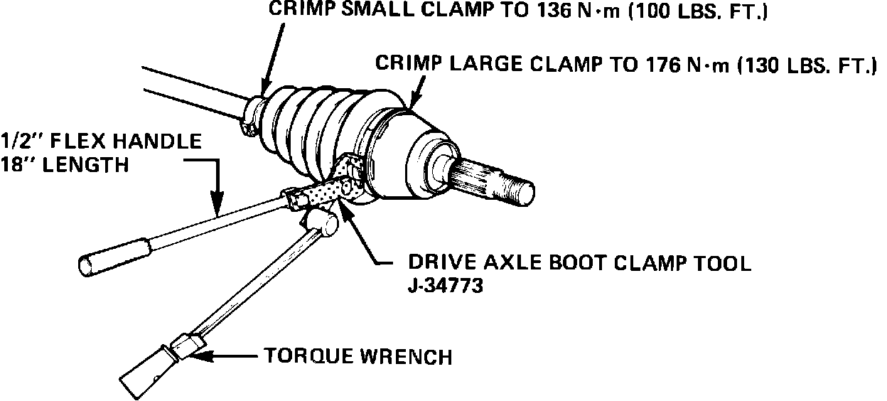
7. Reassemble using the new clamp torque specifications shown in Figure 1, and record the new torque specifications in your Service Manual for future reference.
NOTE: Installation of the clamp requires the use of Kent-Moore clamp tool number J-34773 (shipped to all dealers as part of the 1985 Essential Tool Program). The tool requires the use of an 18" half-inch drive flex handle and a torque wrench, see Figure 1.
FIGURE 2 - Clamp Ears Inspection:
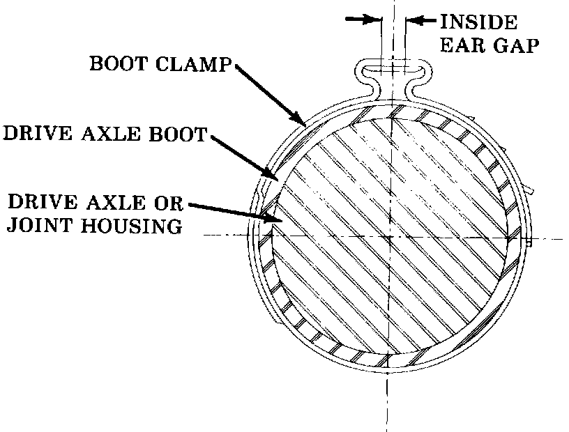
8. After crimping the axle shaft clamp, inspect the clamp ears to verify that a gap still exists between the ears, see Figure 2. This is to ensure that complete clamp load is on the shaft/boot seal connection. If there is no gap between the ears of the clamp, replace the clamp.