Diagnostic Procedure (Century & Grand Prix)
- Perform powertrain diagnostic system check. See POWERTRAIN DIAGNOSTIC SYSTEM CHECK under SELF-DIAGNOSTIC SYSTEM. After performing powertrain diagnostic system check, go to next step.
- Start engine and warm to normal operating temperature. Allow engine idle to stabilize for at least one minute. Using scan tool, monitor O2 HEATER CURRENT. If scan tool displays .25-.85 amp, go to INTERMITTENT TROUBLE CODE DETERMINATION under SELF-DIAGNOSTIC SYSTEM. If scan tool does not display .25-.85 amp, go to next step.
- On Century, check OXY SEN fuse (15-amp) located in underhood fuse block. On Grand Prix, check IGN1-UH fuse (15-amp) located in underhood fuse block. On all models, if fuse is open, go to step 11. If fuse is okay, go to next step.
- Turn engine off. Turn ignition on. Disconnect HO2S 1 harness connector. See Fig 1. Connect a test light between ground and ignition 1 voltage circuit (Pink wire) at HO2S 1 harness connector terminal "D". If test light illuminates, go to next step. If test light does not illuminate, go to step 7.
- Connect test light between ignition 1 voltage circuit (Pink wire) at HO2S 1 harness connector terminal "D" and HO2S 1 heater low control circuit (Black/White wire) at HO2S 1 harness connector terminal "C". Start engine. If test light illuminates, go to step 9. If test light does not illuminate, go to next step.
- Turn ignition off. Connect test light between ground and HO2S 1 heater low control circuit (Black/White wire) at HO2S 1 harness connector terminal "C". Start engine. If test light illuminates, go to step 8. If test light does not illuminate, go to step 12.
- Repair open in ignition 1 voltage circuit (Pink wire) between HO2S 1 harness connector terminal "D" and underhood fuse block. See WIRING DIAGRAMS article. After repairs, go to step 14.
- Repair short to voltage in HO2S 1 heater low control circuit (Black/White wire) between HO2S 1 harness connector terminal "C" and PCM harness connector C2 terminal No. 37. See PCM LOCATION . For PCM terminal identification, see Figure or Figure
. After repairs, go to step 14.
- Check for poor connections or poor terminal tension at HO2S 1 harness connector. If a poor connection is found, replace terminals. After repairs, go to step 14. If no poor connections are found, go to next step.
- Replace HO2S 1. After repairs, go to step 14.
- Repair short to ground in ignition 1 voltage circuit (Pink wire) between HO2S 1 and underhood fuse block. See WIRING DIAGRAMS article. After repairs, go to step 14.
- Check for poor connections or poor terminal tension at PCM harness connector. 1If a problem is found, repair as necessary. After repairs, go to step 14. If a problem is not found, go to next step.
- Replace PCM. Program replacement PCM using required equipment. See PROGRAMMING . After repairs, go to next step.
- Start engine and warm to normal operating temperature. Allow engine idle to stabilize for at least one minute. Using scan tool, monitor O2 HEATER CURRENT. If scan tool displays .25-.85 amp, go to next step. If scan tool does not display .25-.85 amp, go to step 2.
- Using scan tool, clear DTCs. Turn ignition off and wait 30 seconds. Start engine and wait at least 20 seconds. If DTC P0030 runs and passes, go to next step. If DTC P0030 does not run and pass, go to step 2.
- Using scan tool, observe all stored information. If scan tool displays any DTCs that have not been diagnosed, diagnose those DTCs. See DIAGNOSTIC TROUBLE CODE DEFINITIONS . If scan tool does not display any DTCs, system is okay.
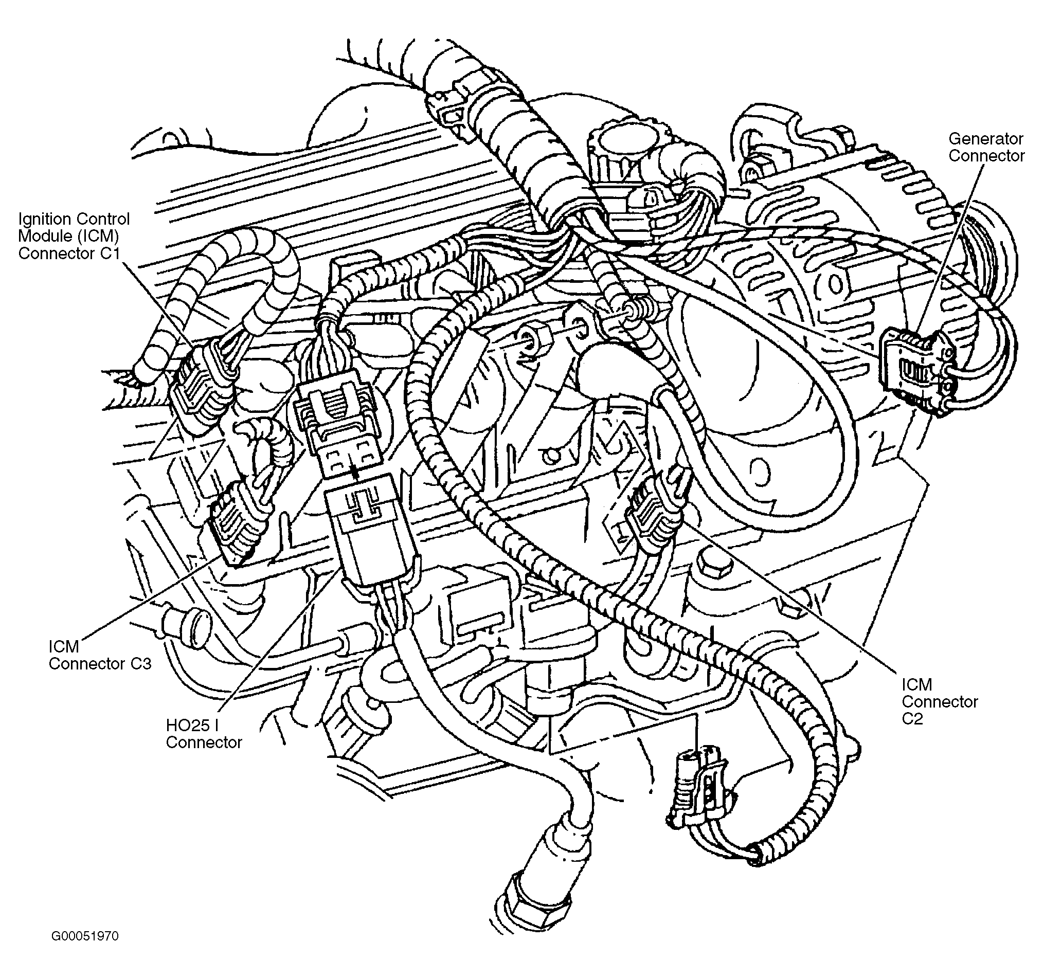 Courtesy of GENERAL MOTORS CORP.