Diagnostic Procedure (Alero, Grand Am, Impala, Malibu & Monte Carlo)
- Perform powertrain diagnostic system check. See POWERTRAIN DIAGNOSTIC SYSTEM CHECK under SELF-DIAGNOSTIC SYSTEM. After performing powertrain diagnostic system check, go to next step.
- Start engine and warm to normal operating temperature. Allow engine idle to stabilize for at least one minute. Using scan tool, monitor O2 HEATER CURRENT. If scan tool displays .25-.85 amp, see INTERMITTENT TROUBLE CODE DETERMINATION under SELF-DIAGNOSTIC SYSTEM. If scan tool does not display .25-.85 amp, go to next step.
- Check ERLS fuse (10-amp) located in underhood fuse block. If fuse is open, go to step 11. If fuse is okay, go to next step.
- Turn engine off. Turn ignition on. Disconnect HO2S 1 harness connector. See Fig 1. Connect a test light between ground and ignition 1 voltage circuit (Brown wire) at HO2S 1 harness connector terminal "D". If test light illuminates, go to next step. If test light does not illuminate, go to step 7.
- Connect test light between ignition 1 voltage circuit (Brown wire) at HO2S 1 harness connector terminal "D" and HO2S 1 heater low control circuit (Black/White wire) at HO2S 1 harness connector terminal "C". Start engine. If test light illuminates, go to step 9. If test light does not illuminate, go to next step.
- Turn ignition off. Connect test light between ground and HO2S 1 heater low control circuit (Black/White wire) at HO2S 1 harness connector terminal "C". Start engine. If test light illuminates, go to step 8. If test light does not illuminate, go to step 12.
- Repair open in ignition 1 voltage circuit (Brown wire) between HO2S 1 and underhood fuse block. See WIRING DIAGRAMS article. After repairs, go to step 14.
- Repair short to voltage in HO2S 1 heater low control circuit (Black/White wire) between HO2S 1 harness connector terminal "C" and PCM harness connector C2 terminal No. 37. See PCM LOCATION . See Figure or Figure
. After repairs, go to step 14.
- Check for poor connections or poor terminal tension at HO2S 1 harness connector. If a poor connection is found, replace terminals. After repairs, go to step 14. If no poor connections are found, go to next step.
- Replace HO2S 1. After repairs, go to step 14.
- Repair short to ground in ignition 1 voltage circuit (Brown wire) between HO2S 1 and underhood fuse block. Replace fuse. See WIRING DIAGRAMS article. After repairs, go to step 14.
- Check for poor connections or poor terminal tension at PCM harness connector. If a problem is found, repair as necessary. After repairs, go to step 14. If a problem is not found, go to next step.
- Replace PCM. Program replacement PCM using required equipment. See PROGRAMMING . After repairs, go to next step.
- Start engine and warm to normal operating temperature. Allow engine idle to stabilize for at least one minute. Using scan tool, monitor O2 HEATER CURRENT. If scan tool displays .25-.85 amp, go to next step. If scan tool does not display .25-.85 amp, go to step 2.
- Using scan tool, observe all stored information. If scan tool displays any DTCs that have not been diagnosed, diagnose those DTCs. See DIAGNOSTIC TROUBLE CODE DEFINITIONS . If scan tool does not display any DTCs, system is okay.
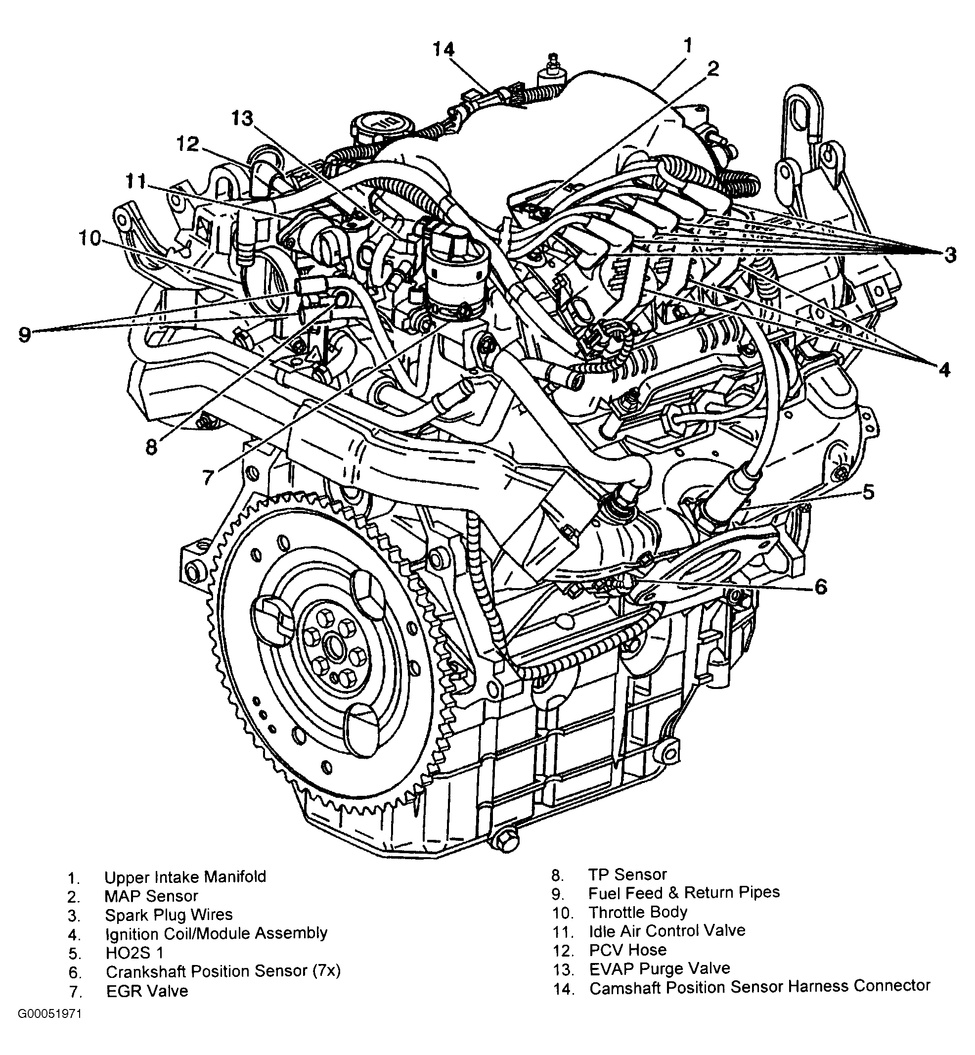 Courtesy of GENERAL MOTORS CORP.