Twilight Sentinel Inoperative
- If diagnostic system check was performed, go to next step. If diagnostic system check was not performed, go to DIAGNOSTIC SYSTEM CHECK.
- Disconnect LCM 24-pin connector C2. Turn ignition on. Using DVOM, check voltage between LCM harness connector C2 terminal A7 (Pink wire) and ground. If reading is about 12 volts, go to next step. If reading is not about 12 volts, go to step 7).
- While varying twilight delay control from MIN to MAX, check resistance between LCM harness connector C2 terminal A6 (Purple wire) and ground. If resistance is 3.5-200 k/ohms, go to next step. If resistance is not 3.5-200 k/ohms, go to step 8).
- Cover ambient light sensor. Check resistance between LCM harness connector C2 terminal A5 (White wire) and ground. If resistance is greater than 31 k/ohms, go to next step. If resistance is not greater than 31 k/ohms, go to step 11).
- Expose ambient light sensor to a bright incandescent light. Check resistance between LCM harness connector C2 terminal A5 (White wire) and ground. If resistance is less than 23 k/ohms, go to next step. If resistance is not less than 23 k/ohms, go to step 11).
- Replace LCM. See REMOVAL & INSTALLATION
. Perform DIAGNOSTIC SYSTEM CHECK.
- Repair open or short to ground in circuit No. 39 (Pink wire) between LCM connector C2, instrument panel bussed electrical center and underhood bussed electrical center. Perform DIAGNOSTIC SYSTEM CHECK.
- Check for open in circuit No. 1783 (Purple wire) between LCM connector C2 and headlight switch. If circuit is okay, go to next step. If circuit is not okay, go to step 14).
- Check for open in circuit No. 351 (Black/White wire) between headlight switch and ground. If circuit is okay, go to next step. If circuit is not okay, go to step 14).
- Replace headlight switch. Perform DIAGNOSTIC SYSTEM CHECK.
- Check for open or short to ground in circuit No. 278 (White wire) between LCM connector C2 and ambient light sensor. If circuit is okay, go to next step. If circuit is not okay, go to step 14).
- Check for open in circuit No. 351 (Black/White wire) between ambient light sensor and ground. If circuit is okay, go to next step. If circuit is not okay, go to step 14).
- Replace ambient light sensor. See REMOVAL & INSTALLATION
. Perform DIAGNOSTIC SYSTEM CHECK.
- Repair open or short to ground in appropriate circuit. Perform DIAGNOSTIC SYSTEM CHECK.
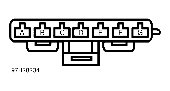 Courtesy of GENERAL MOTORS CORP.
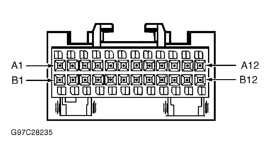 Courtesy of GENERAL MOTORS CORP.