3.3L; Century, Cutlass Ciera & Cutlass Cruiser
- Prior to checking ignition system, check fuel system for cause of no start. See BASIC FUEL SYSTEM CHECKS. Ensure TPS scans less than 2.5 volts. If TPS does not scan less than 2.5 volts, see Code 21 chart in appropriate G - TESTS W/ CODES article in this section. If engine has not been started for at least 8 hours, MAT sensor scan temperature should be close to CTS scan temperature. Disconnect tachometer wire if equipped. A shorted tachometer or tachometer circuit will prevent vehicle from starting.
- Disconnect all injector connectors and install one injector test light in one left bank injector harness connector and one in one of the right injector bank connectors. See Fig 1. Both lights should be off and should blink as engine is cranked. If either injector light is on steady, go to step 6). If lights do not blink at all, go to step 7). If both lights are off and they blink as engine is cranked, go to next step.
- Check for adequate spark with Spark Tester (ST-125). Check for spark on plug wires No. 1, 3 and 5 (one at a time). Leave matching plug wire connected while checking for spark. If spark jumped tester on all plug wires, disconnect all injectors and measure resistance of injector. Injector resistance should be 11.8-12.6 ohms at room temperature. All injectors should measure within .8 ohm of each other. If injectors are okay, check engine for mechanical problems. If spark did not occur on any plug wire, problem is poor ignition module connection or faulty ignition module.
- If spark did not jump tester on one or 2 plug wires, verify that plug wire resistance is less than 30,000 ohms. Replace wires as necessary. If wires are okay, remove coil that did not fire. Connect a test light across ignition module terminals for problem coil.
- Crank engine. If test light flashes, check for poor coil-to-module connections. If connections are okay, replace faulty coil. If test light does not flash, replace ignition module. Also check primary coil resistance. If resistance is not .5-.9 ohm, replace coil.
- Turn ignition off. Disconnect ECM Black C-D connector. Turn ignition on. If all lights are now off, replace ECM. If any lights are still on, repair short to ground in that injector drive circuit.
- Remove injector test lights. Turn ignition on. Using a test light connected to ground, check for battery voltage on Pink/Black wire of injector harness. If test light is on, go to next step. If test light is off, check 20-amp INJ fuse. If fuse is blown, repair short to ground and replace fuse. If fuse is okay, check power supply to fuse and circuit between fuse and injector harness connector.
- Turn ignition off. Disconnect ignition module connector. Turn ignition on. With test light connected to ground, check for battery voltage at ignition module harness connector terminal "M". If test light is not on, repair open in ignition module power supply. If test light is on, install injector test light in any injector harness connector. Connect test light to battery voltage and repeatedly touch terminal "C" of the ignition module harness connector. Injector test light should flash each time test light is touched to terminal "C". If injector test light flashes, go to step 10).
- If injector test light does not flash, turn ignition off. Disconnect ECM Black C-D connector. Turn ignition on. Backprobe ECM injector drive terminals with a DVOM connected to ground. Battery voltage should be present at both driver terminals. If battery voltage is not present, repair open in that circuit. If battery voltage is present, problem is open or shorted circuit No. 430, poor connection at ECM injector driver terminals or faulty ECM.
- Turn ignition off. Reconnect ignition module harness connector. Disconnect dual crank sensor connector. Turn ignition on. Using a DVOM, measure voltage between terminals "C" and "D" of sensor connector. If 10-12 volts is present, go to next step. If 10-12 volts is not present, problem is poor connection at ignition module connector, open or short to ground in circuit No. 644 or 645 or faulty ignition module.
- Turn ignition off. Disconnect No. 6 plug wire from coil tower. NEVER crank engine with wire off of coil. Damage to coil or module may occur. Install Spark Tester (ST-125) onto spark plug wire. Clamp spark tester to coil tower. Install injector test light into any injector harness connector.
- Jumper dual crank sensor harness connector terminals "A" and "B" together. Turn ignition on. DO NOT crank engine. Using a test light connected to ground, momentarily touch dual crank sensor harness terminal "A" while noting injector test light and spark tester.
- If injector test light does not blink and spark tester does not have spark, problem is poor connection at ignition module or faulty ignition module. If injector test light flashes and spark tester has spark, problem is poor connection at dual crank sensor or faulty dual crank sensor. Inspect dual crank sensor and harmonic balancer interrupter rings for damage.
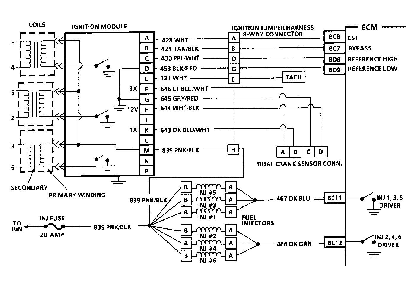 Courtesy of GENERAL MOTORS CORP.