Instrument Cluster C1 & C2 Connector Pin Test
- Remove instrument cluster. See INSTRUMENT CLUSTER
in REMOVAL and INSTALLATION section of this article. Place ignition switch in "RUN" position (except for resistance measurements). Make all resistance measurements to ground with negative battery cable disconnected.
- Make all measurements to ground unless a specific terminal number is given. If voltage or resistance is NOT correct at a terminal, check circuit for malfunction using appropriate test. See Fig 1
and Figure
.
- If correct voltage or resistance is found at terminals, and the function that uses those terminals is incorrect, check instrument cluster printed circuit and bulbs. If printed circuit and bulbs are okay, replace the instrument cluster.
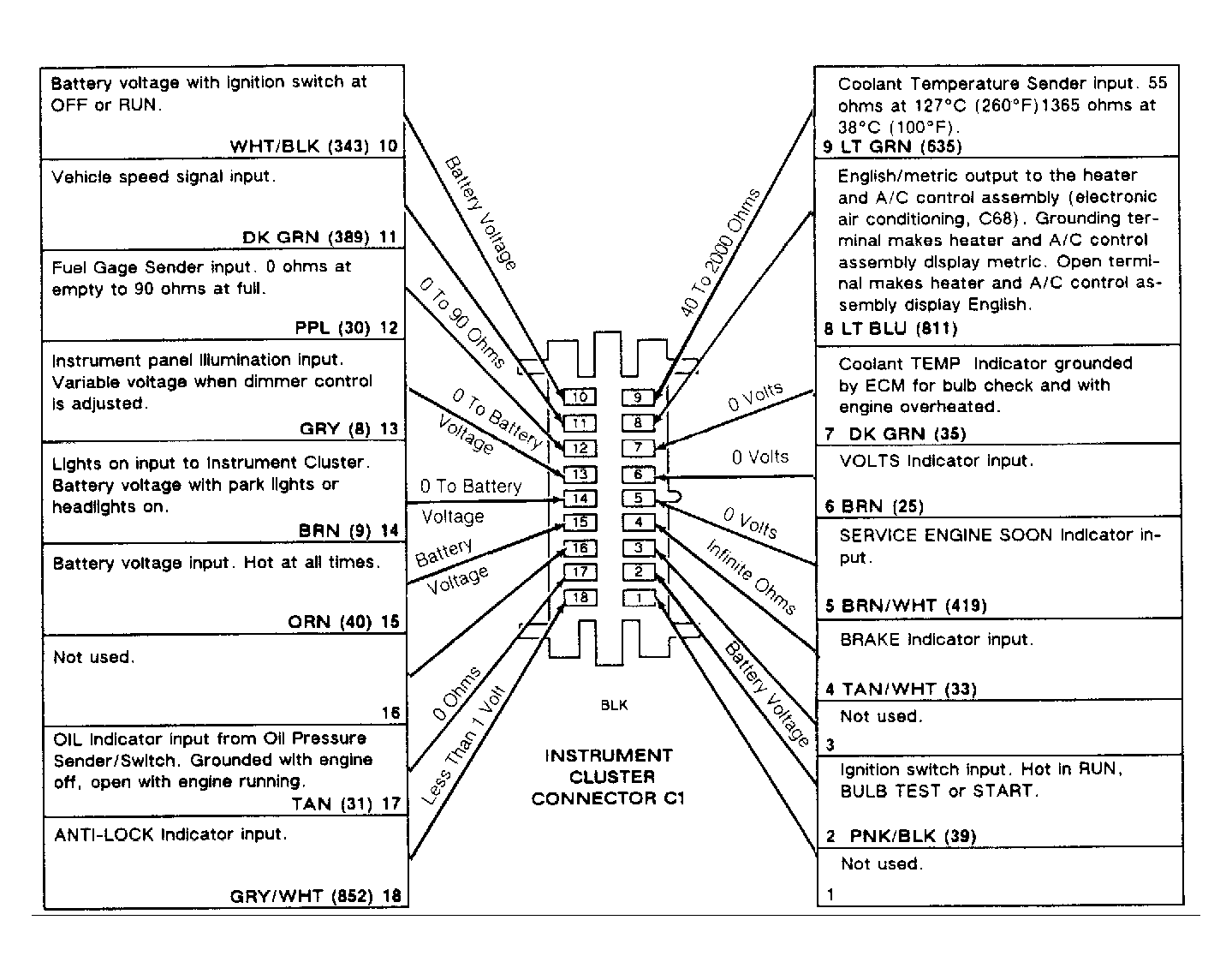 Courtesy of GENERAL MOTORS CORP.
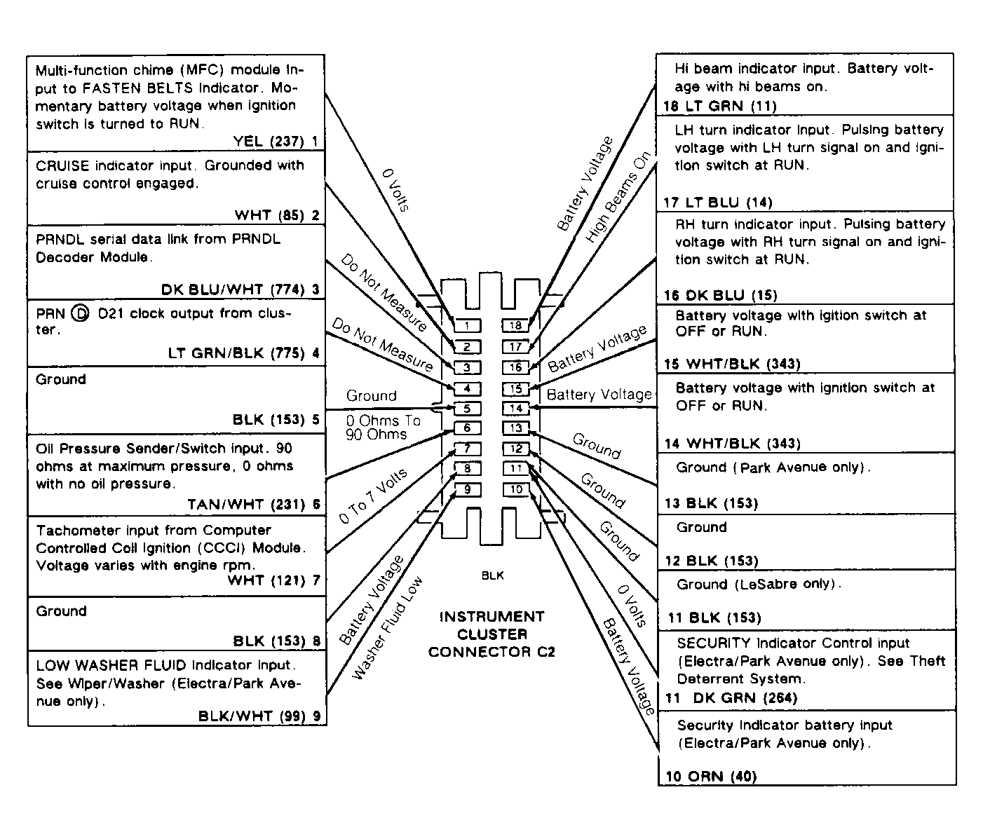 Courtesy of GENERAL MOTORS CORP.