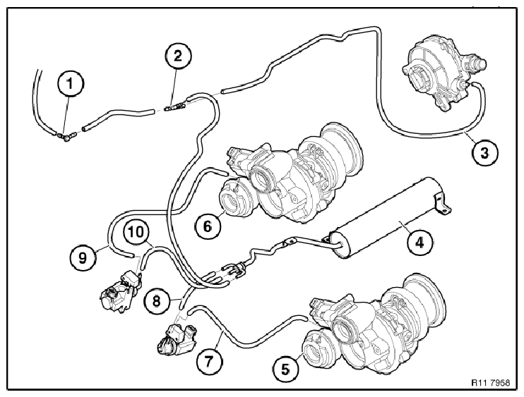
11 65 Connection diagram, vacuum activation (N63)
 Courtesy of BMW OF NORTH AMERICA, INC.
- 1 Connection (1) black
to exhaust flaps.
- 2 Distributor element (2), vacuum pump/vacuum reservoir (4).
- 3 Vacuum line (3) black
to vacuum pump.
- 4 Vacuum reservoir (4) with three connections.
- 5 Connection, vacuum unit (wastegate), bank 2, cylinders 5 to 8.
- 6 Connection, vacuum unit (wastegate), bank 1, cylinders 1 to 4.
- 7 Vacuum hose (7) yellow
up to 7/10 at vacuum unit connection (5) to pressure converter (OUT), bank 2 cylinders 5 to 8.
- 7 Vacuum hose (7) (as of 7/10, the vacuum line is plastic), vacuum unit connection (5) to the pressure converter (OUT), bank 2 cylinder 5 to 8.
- 8 Vacuum hose black
to vacuum reservoir connection to pressure converter (VAC) bank 2 cylinders 5 to 8.
- 9 Vacuum hose (9) up to 7/10 red
at vacuum unit connection (6) to pressure converter (OUT), bank 1 cylinders 1 to 4.
- 9 Vacuum hose (9) (as of 7/10 red
, the vacuum line is plastic), vacuum unit connection (6) to pressure converter (OUT), bank 1 cylinders 1 to 4.
- 10 Vacuum hose black
to vacuum reservoir connection to pressure converter (VAC) bank 1 cylinders 1 to 4.