- Remove both cylinder head covers. Removing fan coupling with fan wheel and fan cowl. Remove non-return valve for cylinders No. 1-6. Remove both distributor housings. If necessary, remove sensor for cylinder recognition (camshaft sensor).
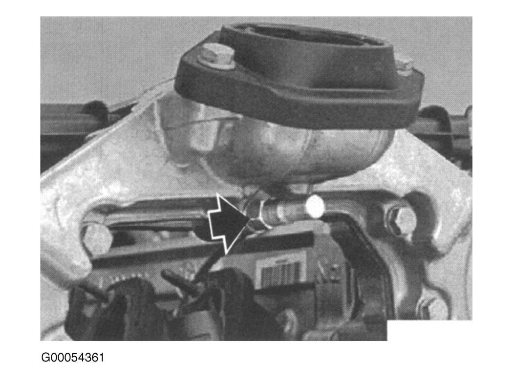
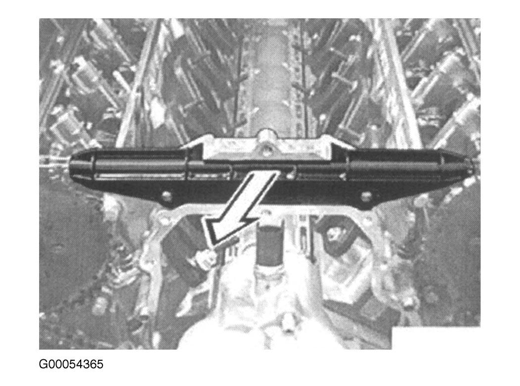
- Remove bolt on oil drip tray guide. Remove bolt cover from oil filler plug and unfasten bolt. Remove bolt from bracket for pipe on secondary air induction. Remove bolts for bracket for secondary air induction pipe. Remove top section of timing case. Remove guide rail from timing chain. Turn central bolt to rotate crankshaft in normal direction of rotation until piston of first cylinder is at TDC. See Fig 1
-Fig 6
.
NOTE:
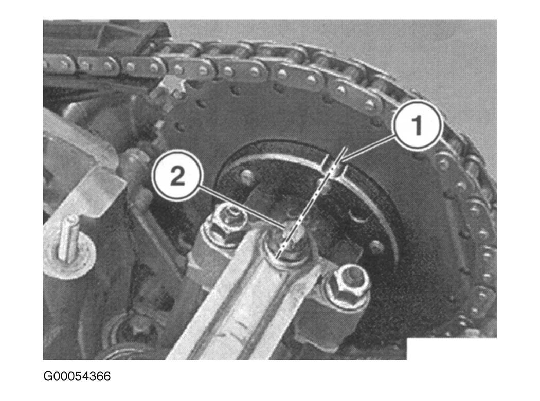
With first cylinder in TDC position, recess in flange on camshaft is aligned with oil injector strip.
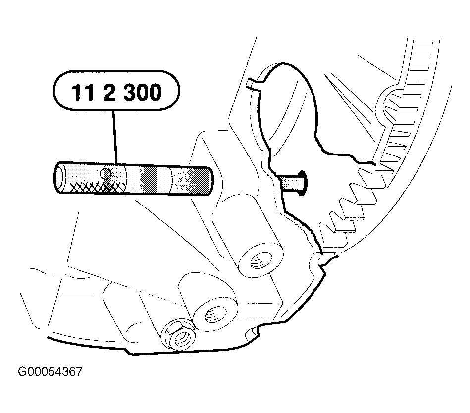
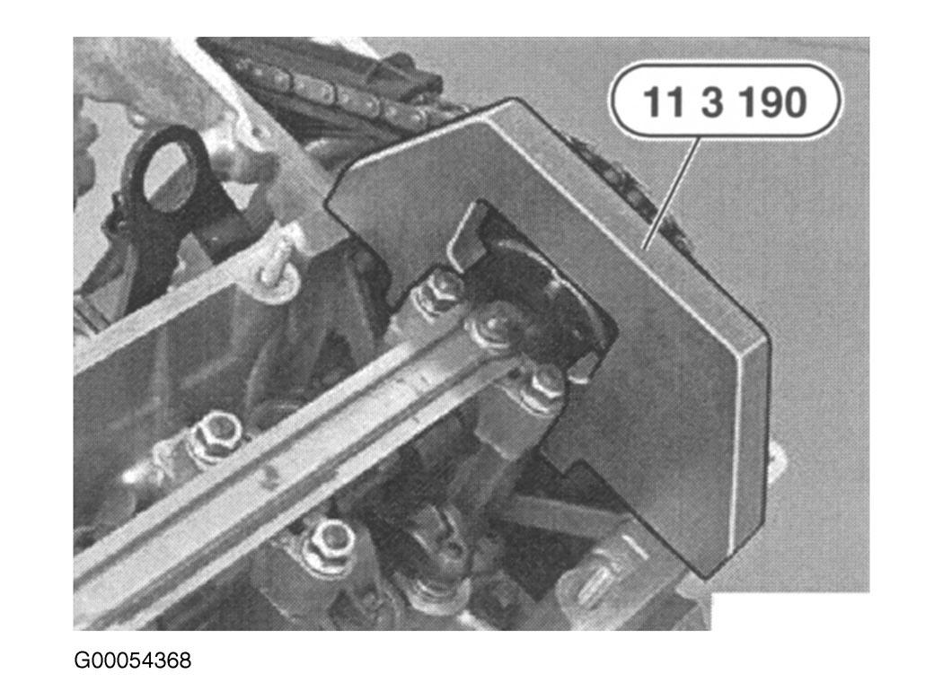
- Remove dust cover from locating bore. Secure crankshaft in TDC position with Lock Pin (11 2 300). Secure both camshafts in TDC firing position with Camshaft Adjuster (11 3 190). Press off retaining cap from chain tensioner with screwdriver. See Fig 7
-Fig 9
.
CAUTION:
Remove lock pin before operating engine.
NOTE:
Crankshaft and camshaft remain secured until completion of conversion work.
 Courtesy of BMW OF NORTH AMERICA, INC.
 Courtesy of BMW OF NORTH AMERICA, INC.
 Courtesy of BMW OF NORTH AMERICA, INC.
 Courtesy of BMW OF NORTH AMERICA, INC.
 Courtesy of BMW OF NORTH AMERICA, INC.
 Courtesy of BMW OF NORTH AMERICA, INC.
 Courtesy of BMW OF NORTH AMERICA, INC.
 Courtesy of BMW OF NORTH AMERICA, INC.
 Courtesy of BMW OF NORTH AMERICA, INC.
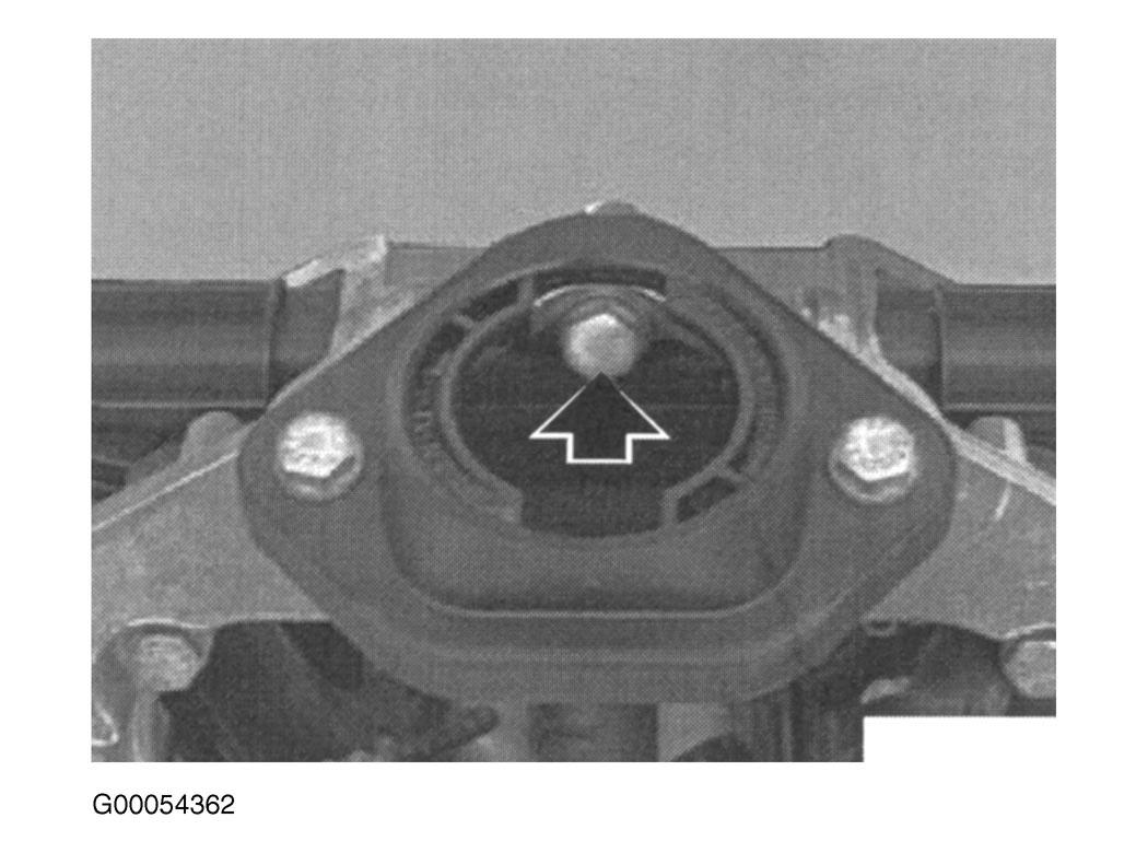
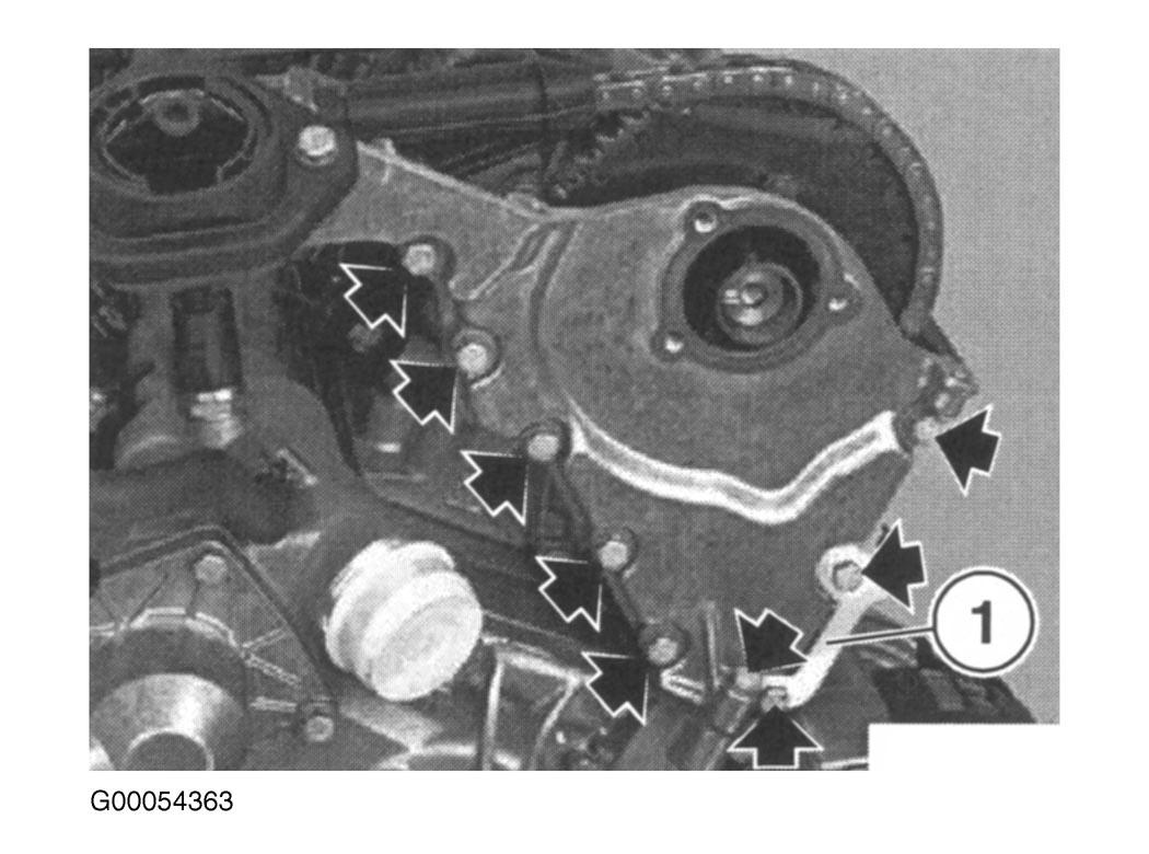
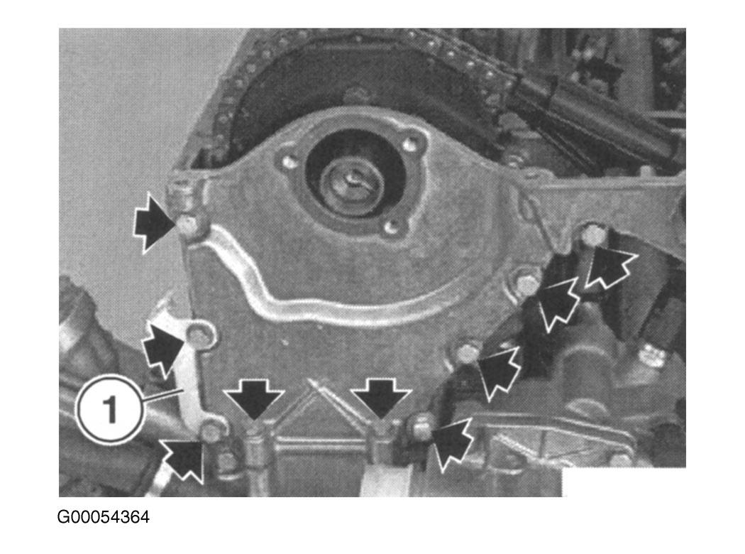
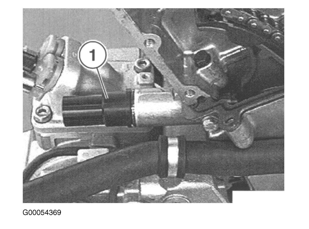
- Loosen lock nut and loosen adjusting bolt a few turns. Carefully unbolt and remove plug. Remove bolts on left and right sprocket wheels. Secure chain to prevent it from dropping. Remove bolt on sliding rail. Pull sliding rail upwards to remove and withdraw lower retaining tab. Loosen bolts. Lift timing case upward to remove. See Fig 10
-Fig 14
.
CAUTION:
Screw plug is spring-loaded. Compression spring may jump out.