Heat Pump Valve Unit, Disassembling and Assembling
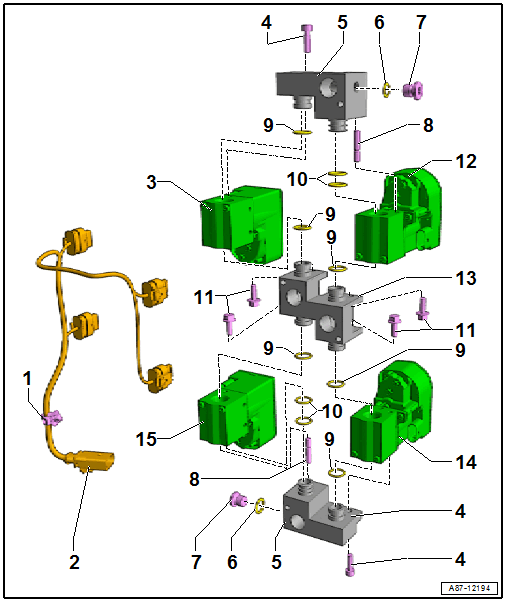 Courtesy of AUDI OF AMERICA, LLC
- Wiring Harness Bracket
- Valve Block Wiring Harness
- Label the routing before removal
- Make sure the connectors are assigned correctly to the valves. Refer to Wiring Harness on Valve Block, Connection Diagram .
- The valve block valves are currently identical in construction. They are assigned through the connector assignment for the wiring harness connectors and are activated accordingly by the Thermal Management Control Module -J1024-. Refer to Wiring Diagram.
- Refrigerant Shut-Off Valve 2 -N640-
- Mark before removal for allocation later
- The valve block valves are currently identical in construction. They are assigned through the connector assignment for the wiring harness connectors and are activated accordingly by the Thermal Management Control Module -J1024-. Refer to Wiring Diagram.
- Bolt
- Outer Connection Block
- Seal
- Replace after removing. Refer to the Parts Information for the version.
- Plug
- 22 Nm
- Replace after removing. Refer to the Parts Information for the version.
- Alignment Pin with Threads
- 4 Nm
- Check for the correct installation position
- O-Ring
- Replace after removing; version. Refer to REFRIGERANT CIRCUIT SEALS
and the Parts Information.
- Lubricate lightly with refrigerant oil before installing
- O-Ring
- Replace after removing; version. Refer to REFRIGERANT CIRCUIT SEALS
and the Parts Information.
- Lubricate lightly with refrigerant oil before installing
- Bolt
- Refrigerant Shut-Off Valve 4 -N642-
- Mark before removal for allocation later
- The valve block valves are currently identical in construction. They are assigned through the connector assignment for the wiring harness connectors and are activated accordingly by the Thermal Management Control Module -J1024-. Refer to Wiring Diagram.
- Inner Connection Block
- Refrigerant Shut-Off Valve 5 -N643-
- Mark before removal for allocation later
- The valve block valves are currently identical in construction. They are assigned through the connector assignment for the wiring harness connectors and are activated accordingly by the Thermal Management Control Module -J1024-. Refer to Wiring Diagram.
- Refrigerant Shut-Off Valve 3 -N641-
- Mark before removal for allocation later
- The valve block valves are currently identical in construction. They are assigned through the connector assignment for the wiring harness connectors and are activated accordingly by the Thermal Management Control Module -J1024-. Refer to Wiring Diagram.