Fuel Gauge And Engine Coolant Temperature Gauge, Troubleshooting
Fuel gauge, inaccurate or does not work
 Courtesy of AUDI OF AMERICA, LLC Courtesy of AUDI OF AMERICA, LLC
|
- All fuses OK according to wiring diagram
| |
|
|
|
|
|
|
|
|
|
|
|
|
|
|
|
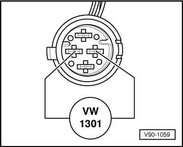
-- Open trunk and remove screws from fuel tank cover-- Remove fuel tank cover-- Remove connector (arrow) from fuel level sensor-- Using connector test kit VW 1594, connect tester VW 1301 to fuel level sensor connector as shown-- Set VW 1301 to 58 (corresponds to approx. 40 ohms (Ω) resistance)-- Switch ignition ON
- Fuel gauge must read full (approx. 21.1 gallons, 80 liters)
|
| Yes |
|
|
No |
| |
|
|
|
|
|
|
|
|
|
|
|
|
|
|
|
| Fuel Level Sensor faulty |
|
|
|
|
Go to A |
| -- Replace Fuel Level Sensor |
|
|
|
|
|
|
|
| |
|
|
|
|
|
|
|
|
|
|
|
|
|
|
| |
|
|
End |
|
|
|
|
|
|
|
|
|
|
|
| |
|
|
|
|
|
|
|
|
|
|
|
|
|
|
|
| |
|
|
|
|
|
|
A |
|
|
|
|
|
|
|
| |
|
|
|
|
|
|
|
|
|
|
|
|
|
|
|
- Leave tester VW 1301 connected to fuel level sensor connector and tester value set to 58
-- Remove instrument cluster INSTRUMENT CLUSTER -- Disconnect red and green 26-point connectors from instrument cluster-- Check connectors for bent terminals, repair as necessary-- Connect adapter harness : VAG1598/4
to red 26-point instrument cluster connector-- Reconnect green 26-point connector to instrument cluster-- Set digital multimeter (Fluke 83 or equivalent) to measure resistance (Ω)-- Connect multimeter between sockets 10 and 3 of VAG 1598 test box
|
| Yes |
No, ∞ Ω (no continuity) is displayed |
| |
|
|
|
|
|
|
|
|
|
|
|
|
|
|
|
| |
|
Go to B |
|
|
|
-- Check wiring to fuel level sensor for open circuit according to wiring diagram, repair as necessary |
|
| |
|
|
|
|
|
|
|
|
|
| |
|
|
|
|
|
|
|
|
|
|
|
|
|
|
|
| |
|
|
|
|
|
|
|
|
|
|
End |
|
|
|
| |
|
|
|
|
|
|
|
|
|
|
|
|
|
|
|
| |
|
|
B |
|
|
|
|
|
|
|
|
|
|
|
| |
|
|
|
|
|
|
|
|
|
|
|
|
|
|
|
- Leave tester VW 1301 connected to fuel level sensor connector
- Keep VW 1301 set to 58
-- Set digital multimeter (Fluke 83 or equivalent) to volt range |
|
|
|
|
|
|
| |
|
|
|
|
|
|
|
|
|
|
|
|
|
|
|
| -- Connect multimeter between socket 10 (-) of VAG 1598 test box and fuel gauge terminal -1- → illustration 90-864
|
| Yes |
No, over 4.6V displayed |
| |
|
|
|
|
|
|
|
|
|
|
|
|
|
|
|
| |
Fuel gauge faulty |
|
Printed circuit board faulty |
| |
-- Replace fuel gauge FUEL GAUGE |
|
-- Replace printed circuit board PRINTED CIRCUIT |
| |
|
|
|
|
|
|
|
|
|
|
|
|
|
|
|
| |
|
|
End |
|
|
|
|
|
|
End |
|
|
|
| |
|
|
|
|
|
|
|
|
|
|
|
|
|
|
|
Engine Coolant Temperature (ECT) gauge, inaccurate or does not work
- All fuses OK according to wiring diagram
 Courtesy of AUDI OF AMERICA, LLC Courtesy of AUDI OF AMERICA, LLC
|
| |
|
|
|
|
|
|
|
|
|
|
|
|
|
|
-- Remove connector from electronic Engine Coolant Temperature (ECT) thermal switch -F76-
- Thermal switch located on coolant pipe behind right cylinder head
-- Connect tester VW 1301 between terminal T of thermal switch connector and Ground (GND)-- Set VW 1301 to 58
- Value 58 on VW 1301 corresponds to approx. resistance 40 ohms (Ω)
-- Switch ignition ON
- Engine coolant temperature gauge must display approx. 230°F (110°C)
|
| Yes |
No |
| |
|
|
|
|
|
|
|
|
|
|
|
|
|
|
|
| Electronic Engine Coolant Temperature (ECT) thermal switch -F76- faulty |
|
|
|
|
| -- Replace electronic thermal switch |
|
|
|
|
|
| |
|
|
|
|
|
|
|
|
|
|
|
|
|
|
|
| |
|
|
End |
|
|
|
|
|
Go to next article |
| |
|
|
|
|
|
|
|
|
|
|
|
|
|
|
|
| |
|
|
|
|
|
|
|
|
|
|
|
|
|
|
|
|
|
|
|
|
|
- Leave VW 1301 connected between terminal T of electronic thermal switch connector and GND, keep VW 1301 set to 58
-- Remove instrument cluster INSTRUMENT CLUSTER -- Disconnect red and green 26-point connectors from instrument cluster-- Check connectors for bent terminals, repair as necessary-- Connect adapter harness : VAG1598/4
to green 26-point instrument cluster connector-- Reconnect red 26-point connector to instrument cluster-- Set digital multimeter (Fluke 83 or equivalent) to measure resistance (Ω)-- Connect multimeter between sockets 11 and 16 of VAG 1598 test box
- Must be approx. 40 ohms (Ω)
|
| Yes |
|
No, ∞ Ω (no continuity) is displayed |
| |
|
|
|
|
|
|
|
|
|
|
|
|
|
|
|
|
|
|
|
|
|
| |
|
|
Go to A |
|
|
|
|
-- Check wiring to electronic Engine Coolant Temperature (ECT) thermal switch for open circuit according to wiring diagram, repair as necessary |
| |
|
|
|
|
|
|
|
|
|
|
| |
|
|
|
|
|
|
|
|
|
|
|
|
|
|
|
|
|
|
|
|
|
| |
|
|
|
|
|
|
|
|
|
|
|
|
|
|
|
End |
|
|
|
|
| |
|
|
|
|
|
|
|
|
|
|
|
|
|
|
|
|
|
|
|
|
|
| |
|
|
|
|
|
|
A |
|
|
|
|
|
|
|
| |
|
|
|
|
|
|
|
|
|
|
|
|
|
|
|
-- Remove adapter harness : VAG1598/4
from instrument cluster (green connector)-- Remove cover from rear of instrument cluster COVER -- Reconnect adapter harness : VAG1598/4
to green 26-point instrument cluster connector-- Set digital multimeter (Fluke 83 or equivalent) to measure resistance (Ω)-- Connect multimeter to Engine Coolant Temperature (ECT) gauge terminals -1- and -2- → illustration 90-865
- Must be approx. 40 ohms (Ω)
|
| Yes |
No, ∞ Ω (no continuity) is displayed |
| |
|
|
|
|
|
|
|
|
|
|
|
|
|
|
|
| |
Printed circuit board faulty |
|
|
ECT gauge faulty |
|
| |
-- Replace printed circuit board PRINTED CIRCUIT |
|
|
-- Replace ECT gauge COOLANT TEMPERATURE GAUGE |
|
| |
|
|
|
|
|
|
|
|
|
|
|
|
|
|
|
| |
|
|
End |
|
|
|
|
|
|
End |
|
|
|
| |
|
|
|
|
|
|
|
|
|
|
|
|
|
|
|
Fuel gauge and Engine Coolant Temperature (ECT) gauge, both inaccurate or do not work
- All fuses OK according to wiring diagram
| |
|
|
|
|
|
|
|
|
|
|
|
|
|
|
|
|
|
|
|
|
|
| -- Remove instrument cluster INSTRUMENT CLUSTER -- Remove red and green 26-point connectors from instrument cluster-- Check connectors for bent terminals, repair as necessary-- Connect adapter harness : VAG1598/4
to red 26-point instrument cluster connector-- Connect adapter harness to VAG 1598 test box-- Reconnect green 26-point connector to instrument cluster-- Set multimeter (Fluke 83 or equivalent) to volt range-- Connect multimeter between sockets 10 (-) and 11 (+) of VAG 1598 test box-- Switch ignition ON
|
| Yes |
No |
| |
|
|
|
|
|
|
|
|
|
|
|
|
|
|
|
|
|
|
|
|
|
| |
|
|
Go to A |
|
|
|
|
-- Check wiring for open circuit according to wiring diagram, repair as necessary |
| |
|
|
|
|
|
|
|
|
|
|
|
|
|
|
|
|
|
|
|
|
|
| |
|
|
|
|
|
|
|
|
|
|
|
|
|
|
|
End |
|
|
|
|
| |
|
|
|
|
|
|
|
|
|
|
|
|
|
|
|
|
|
|
|
|
|
| |
|
|
|
|
|
|
A |
|
|
|
|
|
|
|
| |
|
|
|
|
|
|
|
|
|
|
|
|
|
|
|
| -- Switch ignition OFF-- Connect multimeter (Fluke 83 or equivalent) between terminals -1- (+) and -2- (-) of voltage stabilizer → illustration 90-1123-- Switch ignition ON
|
| Yes |
No |
| |
|
|
|
|
|
|
|
|
|
|
|
|
|
|
|
| |
|
|
|
|
|
|
|
Printed circuit board faulty |
| |
|
|
|
|
|
|
|
-- Replace printed circuit board PRINTED CIRCUIT |
| |
|
Go to B |
|
|
|
|
|
|
|
|
|
|
| |
|
|
|
|
|
|
|
|
|
|
End |
|
|
|
| |
|
|
|
|
|
|
|
|
|
|
|
|
|
|
|
| |
|
|
|
|
|
|
B |
|
|
|
|
|
|
|
| |
|
|
|
|
|
|
|
|
|
|
|
|
|
|
|
| -- Switch ignition OFF-- Connect multimeter (Fluke 83 or equivalent) between terminals -3- (+) and -2- (-)-- Switch ignition ON
|
| Yes |
No |
| |
|
|
|
|
|
|
|
|
|
|
|
|
|
|
|
| |
Printed circuit board faulty |
|
Voltage stabilizer faulty |
| |
-- Replace printed circuit board PRINTED CIRCUIT |
|
-- Replace printed circuit board PRINTED CIRCUIT |
| |
|
|
|
|
|
|
|
|
|
|
|
|
|
|
|
| |
|
|
End |
|
|
|
|
|
|
End |
|
|
|
| |
|
|
|
|
|
|
|
|
|
|
|
|
|
|
|