Driver Seat Cannot Be Adjusted
Checking river's seat voltage supply
 Courtesy of AUDI OF AMERICA, LLC Courtesy of AUDI OF AMERICA, LLC
|
| |
|
|
|
|
|
|
|
|
|
|
|
|
|
|
|
| Driver's seat voltage supply, checking |
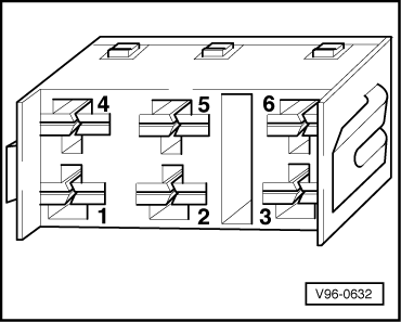
| -- Remove front seat fasteners, and raise front of seat for access to connector-- Disconnect 6-point connector (brown) from driver's seat-- Set multimeter (Fluke 83 or equivalent) to measure resistance (Ω) and connect test leads alternately between terminal 4 of 6-point connector and Ground (GND), then between terminal 5 of 6-point connector and GND
|
| If YES |
If NO |
| |
|
|
|
|
|
|
|
|
|
|
|
|
|
|
|
| |
Go to A next chart |
|
|
-- Check and repair wiring according to wiring diagram |
| |
|
|
|
|
|
|
|
|
|
|
|
|
|
|
|
| |
|
|
|
|
|
|
|
|
|
End |
|
|
|
| |
|
|
|
|
|
|
|
|
|
|
|
|
|
|
|
| |
|
|
|
|
|
|
|
|
|
A |
|
|
|
|
|
|
|
|
|
|
| |
|
|
|
|
|
|
|
|
|
|
|
|
|
|
|
|
|
|
|
|
|
-- Set multimeter (Fluke 83 or equivalent) to measure voltage and connect test leads alternately between terminal 1 of 6-point connector and GND, then between terminal 2 of 6-point connector and GND
- Must be approximately 12 volts
|
| Specified values NOT OK |
Specified values OK |
| |
|
|
|
|
|
|
|
|
|
|
|
|
|
|
|
|
|
|
|
|
|
| -- Check and repair wiring according to wiring diagram |
|
|
-- Connect test leads between terminals 3 and 4 of 6-point connector-- Switch memory control ON
|
| |
|
|
|
|
|
|
|
|
|
|
|
Specified value NOT OK |
Specified value OK |
| |
|
|
|
|
|
|
|
|
|
|
|
|
|
|
|
|
|
|
|
|
|
| |
|
|
|
End |
|
|
|
|
|
|
-- Check and repair wiring according to wiring diagram or, replace memory control button |
|
Go to B next chart |
| |
|
|
|
|
|
|
|
|
|
|
|
|
|
|
| |
|
|
|
|
|
|
|
|
|
|
|
|
| |
|
|
|
|
|
|
|
|
|
|
|
|
|
|
|
| |
|
|
|
|
|
|
|
|
|
B |
|
|
|
|
|
|
|
|
|
|
| |
|
|
|
|
|
|
|
|
|
|
|
|
|
|
|
|
|
|
|
|
|
| Voltage supply relay, checking voltage supply |
-- Reconnect 6-point brown connector-- Disconnect 9-point connector from voltage supply relay-- Set multimeter (Fluke 83 or equivalent) to measure resistance (Ω)-- Connect test leads between terminals 5 of 9-point connector and GND
- Must read 0 Ohm (continuity)
-- Set multimeter to measure voltage-- Connect test leads between terminals 4 and 5 of 9-point connector-- Press memory control ON/OFF switch to ON
- Must read approximately 12 volts
-- Connect test leads between terminals 8 and 5 of 9-point connector
- Must read approximately 12 volts
|
| One or more specified values NOT OK |
All specified values OK |
| |
|
|
|
|
|
|
|
|
|
|
|
|
|
|
|
|
|
|
|
|
|
| -- Check and repair wiring according to wiring diagram |
|
|
|
|
Go to next chart |
|
|
|
|
| |
|
|
|
|
|
|
|
|
|
|
|
|
|
|
|
|
|
|
|
| |
|
|
|
End |
|
|
|
|
|
|
|
|
|
|
|
|
|
|
|
| |
|
|
|
|
|
|
|
|
|
|
|
|
|
|
|
|
|
|
Testing voltage supply relay
 Courtesy of AUDI OF AMERICA, LLC Courtesy of AUDI OF AMERICA, LLC
|
| |
|
|
|
|
|
|
|
|
|
|
|
|
|
|
|
|
|
|
|
|
|
| |
|
|
|
|
|
|
|
|
|
|
Voltage supply relay, checking |
| |
|
|
|
|
|
|
|
|
|
|
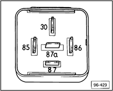
-- Set multimeter (Fluke 83 or equivalent) to measure resistance (Ω)-- Connect test leads between terminals 85 and 86 of relay
- Must be approximately 30 Ω
-- Connect test leads between terminals 30 and 87a of relay
|
| |
|
|
|
|
|
|
|
|
|
|
|
|
|
|
|
|
|
|
|
|
|
-- Connect test leads between terminals 30 and 87 of relay
- Must be ∞ Ω (no continuity)
|
| One or more specified values NOT OK |
All specified values OK |
| |
|
|
|
|
|
|
|
|
|
|
|
|
|
|
|
|
|
|
|
|
|
| |
-- Replace voltage supply relay |
|
|
|
|
Go to next chart |
|
|
| |
|
|
|
|
|
|
|
|
|
|
|
|
|
|
|
|
|
|
|
|
| |
|
|
|
End |
|
|
|
|
|
|
|
|
|
|
|
|
|
|
|
| |
|
|
|
|
|
|
|
|
|
|
|
|
|
|
|
|
|
|
|
|
Checking memory control switch
 Courtesy of AUDI OF AMERICA, LLC Courtesy of AUDI OF AMERICA, LLC
|
| Memory control switch, checking |
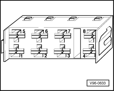
-- Reinstall voltage supply relay-- Open driver's door-- Disconnect 8-point connector -D- (brown) located on seat control module-- Set multimeter (Fluke 83 or equivalent) to measure resistance (Ω)-- Connect test leads between terminal -1- of 8-point connector -D- and GND-- Press memory control ON/OFF switch ON
- Must read 0 Ω (continuity)
-- Set multimeter to measure voltage-- Connect test leads between terminal -8- and GND
-- Connect test leads between terminal -3- and -1- of 8-point connector-- Press and hold memory button switch
- Must read approximately 12 volts
-- Connect test leads between terminal -5- and -1- of 8-point connector-- Press and hold memory control switch button 1
- Must read approximately 12 volts
-- Connect test leads between terminal -2- and -1- of 8-point connector-- Press and hold memory control switch button 2
- Must read approximately 12 volts
|
| |
|
|
|
|
|
|
|
|
|
|
|
|
|
|
|
| |
|
|
|
|
|
Go to next chart |
|
|
|
|
| |
|
|
|
|
|
|
|
|
|
|
|
|
|
|
|
|
|
|
|
|
|
-- Connect test leads between terminals 6 and 1 of 8-point connector -- Press and hold memory control switch button 3
- Must read approximately 12 volts
-- Connect test leads between terminals 7 and 1 of 8-point connector -- Press and hold memory control switch button 4
-- Must read approximately 12 volts |
| One or more specified values NOT OK |
All specified values OK |
| |
|
|
|
|
|
|
|
|
|
|
|
|
|
|
|
|
|
|
|
|
|
| -- Check and repair wiring according to wiring diagram or replace memory control switch/button |
|
Seat memory control module, checking GND |
| |
|
-- Set multimeter (Fluke 83 or equivalent) to measure resistance (Ω)-- Connect test leads between terminal 4 of 8-point connector -D- (brown) and GND
- Must read 0 Ω (continuity)
-- Close driver's door
- Must read ∞ Ω (no continuity)
|
| |
|
|
|
|
|
|
|
|
|
|
|
| |
|
|
|
End |
|
|
|
|
|
| |
|
|
|
|
|
|
|
|
|
|
|
| |
|
|
|
|
|
|
|
|
|
|
|
|
|
|
|
|
|
|
|
|
|
| |
|
|
|
|
|
|
|
|
|
|
|
|
|
|
Go to C next chart |
|
| |
|
|
|
|
|
|
|
|
|
|
|
|
|
|
|
|
|
|
|
|
| |
|
|
|
|
|
|
|
|
|
C |
|
|
|
|
|
|
|
|
|
|
| |
|
|
|
|
|
|
|
|
|
|
|
|
|
|
|
|
|
|
|
|
|
| Seat memory control module, checking GND, cont. |
| Specified values NOT OK |
Specified values OK |
| |
|
|
|
|
|
|
|
|
|
|
|
|
|
|
|
|
|
|
|
|
|
| -- Check and repair wiring according to wiring diagram or replace door contact switch |
|
|
Seat adjustment switch, checking voltage supply |
| |
|
-- Reconnect 8-point connector -D- (brown)-- Remove seat adjustment switch-- Disconnect connector to switch-- Set multimeter (Fluke 83 or equivalent) to measure voltage-- Connect test leads first between terminals -2- and -9-, then between terminals -3- and -10- of connector
|
| |
|
|
|
|
|
|
|
|
|
|
|
| |
|
|
|
End |
|
|
|
|
|
|
| |
|
|
|
|
|
|
|
|
|
|
|
| |
|
|
|
|
|
|
|
|
|
|
|
| |
|
|
|
|
|
|
|
|
|
|
One or more specified values NOT OK |
All specified values OK |
| |
|
|
|
|
|
|
|
|
|
|
|
|
|
|
|
|
|
|
|
|
| |
|
|
|
|
|
|
|
|
|
|
|
-- Check and repair wiring according to wiring diagram |
|
Go to D next chart |
| |
|
|
|
|
|
|
|
|
|
|
|
|
|
|
|
|
|
|
|
|
| |
|
|
|
|
|
|
|
|
|
|
|
|
End |
|
|
|
|
|
|
| |
|
|
|
|
|
|
|
|
|
|
|
|
|
|
|
|
|
|
|
|
8-pin connector
Courtesy of AUDI OF AMERICA, LLC
|
6-pin connector
Courtesy of AUDI OF AMERICA, LLC
|
| |
|
|
|
|
|
|
D |
|
|
|
|
|
|
|
| |
|
|
|
|
|
|
|
|
|
|
|
|
|
|
|
| Driver's seat adjustment switch, checking |
-- Disconnect yellow connector -A- (8-point) and red connector -B- (6-point) from control module -- Set multimeter to measure voltage-- Connect one test lead to GND, and in succession connect other test lead to terminals 5, 2, 6, 3 of connector -B- and operate seat switch in following sequence:
- Front of seat up (red connector, terminal 5)
- Front of seat down (red connector, terminal 2)
- Backrest forward (red connector, terminal 6)
- Backrest backward (red connector, terminal 3)
- Must all read approximately 12 volts
-- Repeat procedure on connector -A-, terminals 8, 4, 6, 2, and operate seat switch in following sequence:
- Rear of seat up (yellow connector, terminal 8)
- Rear of seat down (yellow connector, terminal 4)
- Seat forward on track (yellow connector, terminal 6)
- Seat rearward on track (yellow connector, terminal 2)
- Must all read approximately 12 volts
-- Reinstall connectors and switch |
| Specified values NOT OK |
Specified values OK |
| |
|
|
|
|
|
|
|
|
|
|
|
|
|
|
|
| -- Check and repair according to wiring diagram, or replace switch |
|
|
Go to E next chart |
|
|
| |
|
|
|
|
|
|
|
|
|
|
|
|
|
|
|
| |
|
|
End |
|
|
|
|
|
|
|
|
|
|
|
| |
|
|
|
|
|
|
E |
|
|
|
|
|
|
|
| |
|
|
|
|
|
|
|
|
|
|
|
|
|
|
|
| Seat memory control module, checking |
Note: The 6-point blue connector is applicable to vehicles with power headrests. It may be necessary to cut securing tie wraps for control module to gain access to connectors. -- Do not disconnect yellow connector -A- (8-point), red connector -B- (6-point), and green connector -C- (6-point) from seat memory control module when checking -- Set multimeter (Fluke 83 or equivalent) to measure voltage-- Connect one test lead to GND, and in succession connect other test lead to terminals 1, 4 of connector -B- and operate seat switch in following sequence:
- Front of seat up (red connector, terminal 1)
- Front of seat down (red connector, terminal 4)
- Must all read approximately 12 volts
-- Repeat procedure on connector -A-, terminals 7, 3, 5, 1 and operate seat switch in following sequence:
- Rear of seat up (yellow connector, terminal 7)
- Rear of seat down (yellow connector, terminal 3)
- Seat forward on tracks (yellow connector, terminal 5)
- Seat rearward on tracks (yellow connector, terminal 1)
- Must all read approximately 12 volts
|
| |
|
|
|
|
|
|
|
|
|
|
|
|
|
|
|
| |
|
|
|
|
|
Go to -E1- next chart |
|
|
|
|
|
|
| |
|
|
|
|
|
|
-E1- |
|
|
|
|
|
|
|
| |
|
|
|
|
|
|
|
|
|
|
|
|
|
|
|
-- Repeat procedure on connector -C-, terminals 2, 4, and operate seat switch in following sequence:
- Backrest forward (green connector, terminal 2)
- Backrest backward (green connector, terminal 4)
- Must all read approximately 12 volts
|
| One or more specified values NOT OK |
Specified values OK |
| |
|
|
|
|
|
|
|
|
|
|
|
|
|
|
|
| -- Replace seat memory control module |
|
|
Go to F next chart |
|
|
| |
|
|
|
|
|
|
|
|
|
|
|
|
|
|
|
| |
|
|
End |
|
|
|
|
|
|
|
|
|
|
|
| |
|
|
|
|
|
|
|
|
|
|
|
|
|
|
|
| |
|
|
|
|
|
|
F |
|
|
|
|
|
|
|
| |
|
|
|
|
|
|
|
|
|
|
|
|
|
|
|
| Fore/aft, seat height adjustment actuators, checking |
| -- Disconnect black 6-point connector -E- from seat memory control module -- Set multimeter (Fluke 83 or equivalent) to measure resistance (Ω) |
Height adjustment, front -- Connect test leads between terminals 3 and 2 of connector -E--- Using seat adjustment switch, operate height adjustment actuator
- Resistance of actuator varies with seat position
|
Height adjustment, rear -- Connect test leads between terminals 6 and 2 of connector -E--- Using seat adjustment switch, operate height adjustment actuator
- Resistance of actuator varies with seat position
|
| |
|
|
|
|
|
|
|
|
|
|
|
|
|
|
|
| |
|
|
|
|
|
Go to -F1- next chart |
|
|
|
|
|
|
| |
|
|
|
|
|
|
|
|
|
|
|
|
|
|
|
| |
|
|
|
|
|
|
-F1- |
|
|
|
|
|
|
|
| |
|
|
|
|
|
|
|
|
|
|
|
|
|
|
|
Fore/aft adjustment -- Connect test leads between terminals 5 and 2 of connector -E- -- Using seat adjustment switch, operate fore/aft adjustment actuator
- Resistance of actuator varies with seat position
|
| Actuator resistance DOES NOT vary with seat position |
Actuator resistance DOES vary with seat position |
| |
|
|
|
|
|
|
|
|
|
|
|
|
|
|
|
| -- Replace malfunctioning actuator(s) |
|
|
Go to G next chart |
|
|
| |
|
|
|
|
|
|
|
|
|
|
| |
|
|
End |
|
|
|
|
|
|
|
|
|
| |
|
|
|
|
|
|
|
|
|
|
|
|
|
| |
|
|
|
|
|
|
G |
|
|
|
|
|
|
|
| |
|
|
|
|
|
|
|
|
|
|
|
|
|
|
|
| Backrest actuator, checking |
-- Set multimeter (Fluke 83 or equivalent) to measure resistance (Ω)-- Connect test leads between terminals 3 and 6 of connector -C- -- Using backrest adjustment switch, operate backrest actuator
- Do not recline backrest more than 35°
- Resistance of actuator varies with backrest position
-- Reinstall all tie wraps and fasteners |
| Actuator resistance DOES NOT vary with seat position |
Actuator resistance DOES vary with seat position |
| |
|
|
|
|
|
|
|
|
|
|
|
|
|
|
|
| -- Replace backrest actuator |
|
-- Replace backrest adjustment motor |
| |
|
|
|
|
|
|
|
|
|
|
|
|
|
|
|
| |
|
|
End |
|
|
|
|
|
|
End |
|
|
|
| |
|
|
|
|
|
|
|
|
|
|
|
|
|
|
|