Overview - Supercharger
 Courtesy of AUDI OF AMERICA, LLC
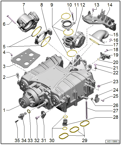
- Supercharger
- Ball Pin
- 5 Nm
- For the engine cover
- Insulation Plate
- Bolt
- O-rings
- Always replace after removing
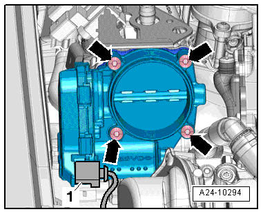
- Bolt
- Tightening specification. Refer to Fig 2.
- Throttle Valve Control Module -J338-
- Intermediate Flange
- O-rings
- Always replace after removing
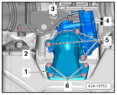
- Bolt
- Tightening specification and sequence. Refer to Fig 3.
- Intermediate Flange
- Regulating Flap Control Unit -J808-
- Bolt
- Bracket
- Connection
- Bolt
- Tightening specification and sequence. Refer to Fig 3.
- O-ring
- Always replace after removing
- Bolt
- Intake Air Temperature Sensor -G42- / Manifold Absolute Pressure Sensor -G71-
- O-ring
- Always replace after removing
- Bleed Screw
- 1.5 to 3.0 Nm
- For the charge air cooler
- Gasket
- Always replace after removing
- Nut
- Charge Air Pressure Sensor/Charge Air Pressure Sensor
- Cylinder bank 1 (right) Charge Air Pressure Sensor -G31- /Intake Manifold Temperature Sensor -G72-
- Cylinder bank 2 (left) Charge Air Pressure Sensor 2 -G447- /Intake Manifold Temperature Sensor 2 -G430-
- Bolt
- O-ring
- Always replace after removing
- Stud Bolt
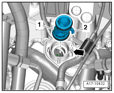
- Connection
- For the crankcase ventilation
- Installation position. Refer to Figure.
- Seals
- Always replace after removing
- O-rings
- Always replace after removing
- Quantity 2 each
- Engine Lifting Eye
- Bolt
- O-ring
- Always replace after removing
- Turbocharger Speed Sensor 1 -G688-
- Bolt
 Courtesy of AUDI OF AMERICA, LLC
 Courtesy of AUDI OF AMERICA, LLC
 Courtesy of AUDI OF AMERICA, LLC